


Brute Elite
Page 37
SECTION 8.
Brute Elite Control Setup
and Operation
The Brute Elite control is an integrated electronic
control that replaces many of the individual components
found on older appliances. The control acts as the
ignition control, pump control, high limit and cascading/
lead lag control and is setup using the display on the
appliance.
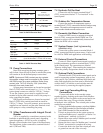
MENU ITEM DEFINITION
F or C Selects temperature units
LBTHODLOD Outdoor reset enable/disable -
enables menu items
LBT Low boiler setpoint during outdoor reset
see Figure 29
HOD High outdoor temperature setpoint
see Figure 29
LOD Low outdoor temperature setpoint
see Figure 29
RMT Add Used for Lead/Lag (follow menus)
LL Lead/Lag enable/disable - enables menu items
HS Hysteresis - temp range between on/off cycles
bL Base Load % - input rate before next boiler fires
Sd Warm weather shut-down temperature
ASC Anti short cycle - minutes of delay between
startup
bAC Future use - Press DONE to exit menu.
PAS Future use - Press DONE to exit menu.
NOTE: When enabling/disabling functions, select "Done" and wait 30
seconds before scrolling.
Table 13. Setup Mode Parameters.
MENU ITEM FUNCTION RANGE DEFAULT
Outlet water Displays the current outlet 55-190°F 120°F
temperature water temperature & allows
the setpoint to be adjusted
Inlet water Displays the current inlet — —
temperature water temperature
Delta T Displays the current — —
temperature rise across
the heat exchanger
DHW water Displays the current DHW 60-182°F 120°F
temperature temperature & allows the
setpoint to be adjusted
Stack Displays the current stack — —
temperature temperature
Outdoor Displays the current outdoor — —
temperature air temperature
LL Displays the current system 60-190°F 120°F
temperature and allows the
setpoint to be adjusted
Firing Rate Displays an indicator of the — —
current firing rate based
upon fan RPM. The actual
firing rate may vary.
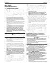
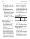
Table 12. User Mode Menu Structure.
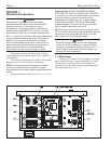
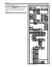
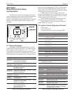
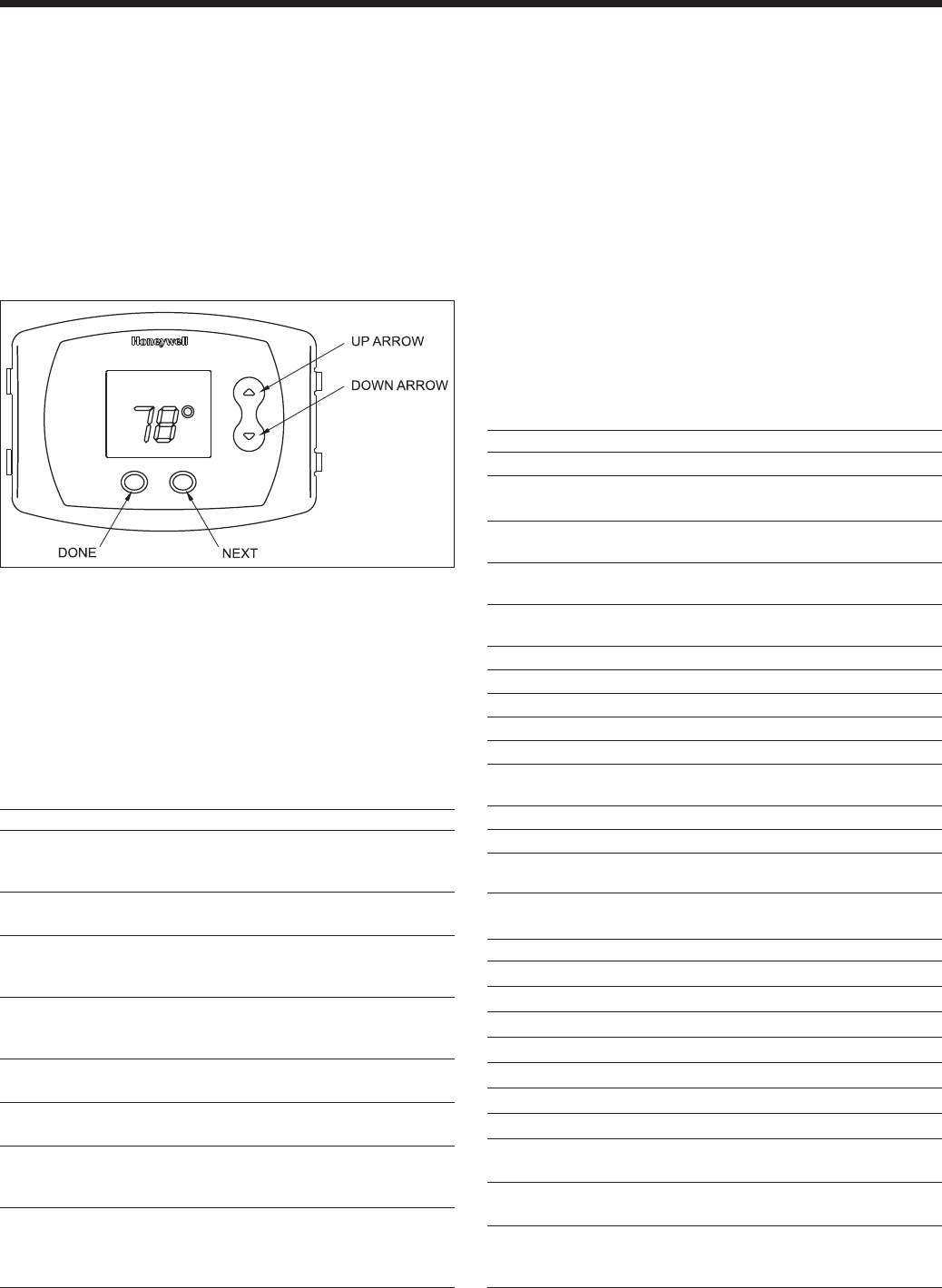
Figure 31. Control Buttons on User Interface.
8.1 Display Navigation
The display is divided into three menu structures,
USER, SETUP and DIAGNOSTIC. The menu structure
and variables in each are shown in Tables 12-14. Once
in a particular menu structure navigation consists of
pressing the next button to scroll from item to item and
then pressing the up and down arrows to change values.
Once the value is adjusted the NEXT or DONE button
can be pressed. The DONE button returns you to the
Home screen. The NEXT button increments the display
to the next item in the menu structure.
USER mode is the home screen shown on the
control. If the display is not in USER mode wait for the
display timeout period to be reached or press the Done
button to return to the USER menu.
SETUP mode is accessed by holding the up and
down arrow keys simultaneously for 3 seconds.
DIAGNOSTIC mode is accessed by holding the
NEXT button for 3 seconds.
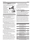
8.2 Ignition Control- Sequence of Events
1. Call for heat
2. Safety chain check
3. Fan starts and waits to achieve prepurge RPM
MENU ITEM DESCRIPTION
mA Display the flame sense signal
Alert codes Displays the current alert code
Lockout code Displays the current lockout code
Outlet Limit Displays outlet temperature limit
DHW limit Displays Domestic Hot Water limit setting
Stack Limit Displays Stack limit setting
Min. firing rate Displays the minimum firing rate allowed
Min. forced Allows the user to force the boiler to fire at
firing rate the minimum firing rate
Max forced Allows the user to force the boiler to fire at
firing rate the maximum firing rate
Rate indicator Displays a indicator of the firing rate based
off of the fan RPM. Actual firing rate may
vary depending upon setup.
Table 14. Diagnostic Mode Menu Structure.