


BRADFORD WHITE CORP.
Page 2
TABLE OF CONTENTS
SECTION 1.
General Information
1.1 Introduction...................................................... 4
1.2 Model Identification ......................................... 4
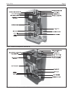
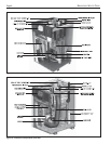
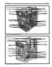
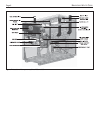
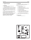
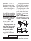
1.3 Appliance Overview ......................................... 4
1.4 Warranty .......................................................... 9
1.5 Unpacking ....................................................... 9
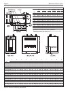
1.6 Dimensions...................................................... 9
SECTION 2.
Locating the Appliance
2.1 Locating the Appliance .................................. 11
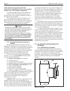
2.2 Locating Appliance for Correct Vent Distance
from Outside Wall or Roof Termination ......... 11
Section 3.
Venting and Combustion Air
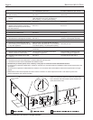
3.1 Combustion Air .............................................. 12
3.1.1 Combustion Air From Room .......................... 12
3.1.2 Ducted Combustion Air ................................. 12
3.2 Venting .......................................................... 13
3.2.1 Venting Requirements Unique to Canada ..... 14
3.3 Locating Vent & Combustion Air Terminals ... 14
3.3.1 Side Wall Vent Terminal ................................ 14
3.3.2 Side Wall Combustion Air Terminal ............... 15
3.3.3 Vertical Vent Terminal ................................... 15
3.3.4 Vertical Combustion Air Terminal .................. 15
3.3.5 Installations in the Commonwealth of
Massachusetts .............................................. 15
3.4 Common Vent Test ....................................... 17
Section 4.
Gas Supply and Piping
4.1 Gas Supply and Piping .................................. 18
Section 5.
Pump Requirements
5.1 Brute Elite Boiler Flow and
Head Requirements ...................................... 19
5.2 Brute Elite Water Heater
Flow and Head Requirements ....................... 19
Section 6A.
Water Connections -
BNTH Boiler
6A.1 BNTH System Piping: Hot Supply Connections20
6A.2 BNTH Cold Water Make-Up .......................... 20
6A.3 Freeze Protection .......................................... 21
6A.4 BNTH Suggested Piping Schematics ............ 21
6A.5 Recognized Chemicals.................................. 21
Section 6B.
Water Connections -
BNTV Water Heater
6B.1 BNTV Water Quality ...................................... 29
6B.2 Piping Requirements ..................................... 29
6B.3 Cold Water Make-Up ..................................... 30
6B.4 Freeze Protection .......................................... 30
6B.5 BNTV Suggested Piping Schematics ............ 30
6B.6 BNTV Suggested Pumps .............................. 30
Section 7.
Electrical Connections
7.1 Main Power ................................................... 32
7.2 Pump Connections ........................................ 33
7.3 24 Vac Transformer with Integral
Circuit Breaker............................................... 33
7.4 Hydronic Call for Heat ................................... 33
7.5 Outdoor Air Temperature Sensor .................. 33
7.6 Domestic Hot Water Connection ................... 33
7.7 System Sensor
(lead lag/cascading operation only)............... 33
7.8 External Control Connections ........................ 33
7.9 Optional Field Connections ........................... 33
7.10 Lead lag/ Cascading Wiring Connections ..... 33
7.11 Wiring Diagrams ............................................ 35
Section 8.
Brute Elite Control Setup and Operation
8.1 Display Navigation ......................................... 37
8.2 Ignition Control - Sequence of Events ........... 37
8.3 Modulation Control ........................................ 38
8.4 Pump Control ................................................ 38
8.5 Anti-Short Cycle (ASC) .................................. 38
8.5 High Limit ...................................................... 38
8.7 Outlet Water Temperature ............................. 38
8.8 Inlet Water Temperature ............................... 38
8.9 Heat Exchanger Temperature Rise ............... 38
8.10 Stack Temperature ........................................ 38
8.11 Domestic Hot Water Temperature ................. 38
8.12 Lead Lag/Cascading ..................................... 38
8.12.1 Lead Lag Setpoint ......................................... 39
8.12.2 Lead Lag Master/Slave Selection .................. 39
8.12.3 Lead Lag Address ......................................... 39
8.12.4 Lead Lag Hysteresis ...................................... 39
8.12.5 Lead Lag Base Load Setting ......................... 39
8.13 Boiler Pump Interrupt .................................... 39