


BRADFORD WHITE CORP.
Page 38
4. Prepurge timer is started once the prepurge RPM is
achieved.
5. Pre ignition time of 2 seconds to check the flame
sensor operation and status. During this period an
intermittent spark can be seen.
6. Trial for ignition period, 4 seconds. The direct
spark ignition switches to constant spark for three
seconds, during which time the gas valve is open.
For the last second of the ignition period direct
spark is de-energized and the flame sensor checks
for established flame. If flame is sensed the control
enters "Run" to satisfy the demand. If flame is not
established the control enters a retrystarting from
step 2. If flame has not been established in the
appropriate number of retries the control will
lockout with a 109 error code.
7. Call for heat complete
8. Gas valve off
9. Fan and pump over run times active to purge the
system
This sequence is the basic operating sequence of
the appliance whether there is a DHW, or hydronic call
for heat.
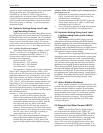
8.3 Modulation Control
The control uses a PID algorithm to adjust the
firing rate of the boiler as the control point is
approached. The goal of the control is to operate at a
minimum firing rate to match the load on the appliance.
This is done by using a setpoint, and on / off
differentials. The control modulates to achieve the
setpoint temperature, which could be several degrees
away from the actual off point. The off point is
calculated by adding the setpoint + off differential. The
setpoint and differentials used in operation is dependent
upon the call for heat being applied. If there is a DHW
call the DHW setpoint and off differentials are used. If
there is a hydronic call the CH setpoint and off
differential is used. When the setpoint + off differential
is achieved the control interrupts appliance firing until
the water temperatures reaches the setpoint - on
differential. Both the hydronic and DHW setpoints are
adjustable through the USER mode menu structure.
8.4 Pump Control
The control can operate three pumps. The boiler
pump is active anytime there is a call for heat applied to
the control. The DHW and system pumps are active
based upon the call and priority of the heat demand
being supplied. When there is a hydronic call supplied
the system pump is active. If there is a DHW call
supplied while the hydronic call is active the system
pump turns off and the DHW turns on. This happens
because of domestic hot water priority, which forces the
control to attempt to satisfy the domestic water demand
prior to the hydronic demand. When the last heat
demand is satisfied the boiler pump enters an overrun
time.
8.5 Anti-Short Cycle (ASC)
The anti short cycle period is started whenever the
gas valve turns off. This period is to help prevent short
cycling. Depending upon the time selected the control
will wait up to 10 minutes before attempting to start the
trial for ignition sequence. The ASC time can be
adjusted by entering setup mode.
8.5 High Limit
The control uses a dual thermistor sensor to
monitor the Brute Elite's maximum temperature. The
high limit sensor is installed in the outlet water. A dual
thermistor sensor is used, so that the two temperatures
can be monitored and compared to confirm accuracy.
The control will automatically reduce the firing of the
Brute Elite to prevent the high limit from tripping. The
high limit setpoint is not adjustable.
8.7 Outlet Water Temperature
The outlet water temperature is a dual thermistor
sensor and is limit rated. The control compares each of
the temperature readings to determine accuracy. The
outlet sensor is used as the primary control point for
high limit, temperature operation, and modulation. The
operating setpoint can be adjusted through the USER
menu structure.
8.8 Inlet Water Temperature
The inlet water temperature uses a single
thermistor sensor and is used to calculate the delta T of
the system.
8.9 Heat Exchanger Temperature Rise
The heat exchanger temperature rise is calculated
from the outlet and inlet sensor temperatures. The result
is displayed in the USER menu structure.
8.10 Stack Temperature
The stack temperature is a dual thermistor sensor
and is limit rated. The control compares each of the
temperature readings to determine accuracy. The stack
sensor is used as a limiting feature to avoid excessive
temperatures in the venting.
8.11 Domestic Hot Water Temperature
The domestic hot water temperature sensor is used
to monitor the DHW demand. The control uses the
DHW sensor to control the operation and modulation
rate of the appliance when there is a DHW demand. The
DHW setpoint can be adjusted through the USER menu
structure.
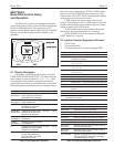
8.12 Lead Lag / Cascading
Lead Lag/Cascading allows multiple boilers to be
connected together and controlled from one common
sensor input. Up to 8 boilers can be connected together
in a single system. To setup Lead/Lag or cascading