


Before making any
connections to the cold water inlet or hot
water outlet, insure that all piping is clean and
free of material or scale. This can usually be
accomplished by “blowing out the pipe.” Any
foreign material or scale entering the water
heater can adversely affect operation and
performance.
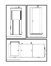
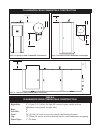
Inlet and Outlet Connections
For ease of service, install unions on the cold
water inlet and hot water outlet of the water
heater. The cold water inlet connection is located
on the lower right side of the water heater. A
manual shutoff valve should be installed
upstream on the cold water source as an isolation
device. The hot water outlet connection is located
on the top center of the water heater. A manual
shutoff valve should be installed downstream on
the hot water outlet source as an isolation device
in case the water heater must be disconnected
from the system.
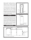
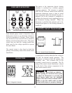
This appliance uses a glass lined steel tank to
store the heated water for use. The storage tank
is constructed in accordance with the ASME
Boiler and Pressure Vessel Code requirements,
stamped and registered with the National Board
of Boiler and Pressure Vessel Inspectors. The
tank is furnished with threaded connections for
cold water inlet, hot water outlet, a relief valve
and a drain connection. The storage tank has a
hand hole for ease of inspection, cleanout and
service. An optional manhole may be specified
for greater ease of inspection. The interior of the
storage tank is glass lined and fired to 1600˚F
(871˚C) to insure a molecular fusing of glass and
steel to protect the steel base metal against
corrosion . A magnesium anode(s) is standard to
help prevent dissipation of the tank material by
electrolytic action.
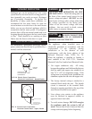
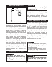
This water heater is supplied with a temperature
and pressure relief valve(s) sized in accordance
with ASME Boiler and Pressure Vessel Code,
Section IV. Some water heaters may be supplied
with an optional pressure only relief valve. The
relief valve(s) is installed in the vertical position
and mounted in the tapping provided in the
storage tank. No valve is to be placed between
the relief valve and the water heater. To prevent
water damage, the discharge from the relief valve
must be piped to a suitable floor drain for
disposal when relief occurs. No reducing
couplings or other restrictions shall be installed in
the discharge line. The discharge line shall allow
complete drainage of the valve and line. Relief
valves should be manually operated at least once
a year. A relief valve that fails to completely
reseat and continues to discharge water must be
immediately replaced with a new, properly sized,
temperature and pressure relief valve.
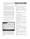
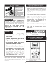
A relief valve that discharges periodically may be
due to thermal expansion in a closed system. A
water heater installed in a closed system, such as
one with a backflow preventer or check valve
installed in the cold water supply, shall be
provided with means to control expansion.
Contact the water supplier or local plumbing
inspector on how to correct this situation.
DO NOT plug or cap the relief valve.
8
STORAGE TANK
NOTE:
When using copper tubing,
solder tubing to an adapter before attaching
to the threaded nipple connection provided
on the water heater. Soldering directly to the
threaded connection may harm a lining in the
nipple or damage the tank lining.
NOTE:
RELIEF VALVE
Avoid contact with hot
discharge water. Insure that no one is in
front of or around the relief valve discharge
line. Make sure that the extremely hot
water manually discharged from the relief
valve will not cause bodily injury or
property damage.
CAUTION:
THERMAL EXPANSION OF WATER