


4. Close and lock the electrical control panel door.
5. Turn on the main electrical power to the
water heater.
6. Temperature control and contactor operation
should be checked by allowing the water
heater to come up to temperature and shut off
automatically.
7. The water heater is now ready continuous
normal operation.
Draining the Water Heater
1. Turn off the main electrical power to the
water heater. If the power disconnect point is
out of sight, lock it in the open (“OFF”)
position and tag to prevent unexpected
application of power.
2. Turn the valve in the water heater’s cold water
supply to the closed or “OFF” position.
3. Turn the valve in the water heater’s hot water
outlet to the closed or “OFF” position.
4. Manually open the temperature and pressure
relief valve to remove any pressure from the
storage tank.
5. Allow the system to cool and then open the
drain valve to empty the storage tank. It will
be necessary to manually hold the
temperature and pressure relief valve in the
open position to break the vacuum in the tank
and allow it to vent and drain. Insure that the
water heater drain is routed to a properly sized
floor drain to allow the water to be removed
from the tank. If a floor drain is not available,
a hose may be attached to the water heater
drain to take the water outdoors.
6. The water heater is now shut down and ready
for service or maintenance.
7. Follow the filling and start up procedure to
place the water heater back into service.
Listed below are items that must be checked to
insure safe reliable operations. Verify proper
operation after servicing.
The temperature and pressure relief valve(s)
should be manually operated at least once a year.
A relief valve that fails to completely reseat after
manual operation and continues to discharge
water must be immediately replaced with a new,
properly sized, temperature and pressure relief
valve.
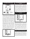
The relief valve(s) should be installed in the
vertical position and mounted in the tapping
provided in the storage tank. No valve should be
placed between the relief valve, and the water
heater. To prevent water damage, the discharge
from the relief valve must be piped to a suitable
floor drain for disposal when relief occurs. No
reducing couplings or other restrictions shall be
installed in the discharge line. The discharge line
shall allow complete drainage of the valve and
line. The discharge line from the relief valve
24
SHUTDOWN PROCEDURE
Any water discharged from
the manually opened relief valve may be hot
and cause a scald injury.
CAUTION:
MAINTENANCE
WARNING:
HAZARD OF ELECTRICAL SHOCK –
Before opening the access panel to perform
service on any electrical component, make
sure the electrical supply to the water
heater is turned “OFF”. Failure to do this
could result in death, serious bodily injury
or property damage.
Label all wires prior to
disconnection when servicing controls.
Wiring errors can cause improper and
dangerous operation.
CAUTION:
TEMPERATURE AND PRESSURE
RELIEF VALVE OPERATION