


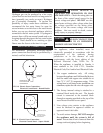
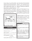
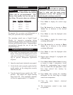
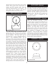

Once power is applied to the temperature
controller the display will countdown from 210
until the display reads zero. All outputs are
de-energized at this time. This countdown
process will repeat each time main power is
interrupted. To avoid viewing this entire
countdown, press the
Select key. The display will
now show normal readings: load (sensed)
temperature and stages energized. At any time
during the programming procedure, the display
will revert back to showing the sensed
temperature and stage status indication 60
seconds after the last programming key is pushed.
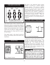
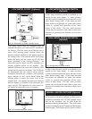
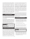
Each stage on the controller has its own
independent set point and differential which are
determined by the programming keys. Each
stage of heating is de-energized as the sensed
temperature reaches the programmed set point.
Each available stage of heating is energized as the
sensed temperature reaches the set point minus
the differential.
EXAMPLE:
Using stage one of the control as an example, the
corresponding load would be energized and
de-energized at the following temperatures based
on the programmed settings.
Settings
Set point: 160
o
F
Differential: 8
o
F
Output Energized
Stage One: Energized at 152
o
F
Output De-energized
Stage One: De-energized at 160
o
F
Each available stage of operation must be
programmed with a set point and a differential. If
two stages are programmed with the same set
point and differential the control will sequence
both stages on and off with only a slight delay
between switching of the stages. The control is
normally programmed with a few degrees
difference between the set point of each stage to
sequence individual stages on as required by
demand. This will allow input to be balanced to
system demand. The exact settings will be
determined by your system hot water
requirements.
Based on your system requirements, determine
the set point and switching differential for each
stage of operation and enter into the worksheet
below.
Pro
gramming W
orksheet
Stage 1:
Set Point 1 ___________ Off at ___________
Differential 1 ________ On at __________
Stage 2:
Set Point 2 ___________ Off at ___________
Differential 2 ________ On at __________
Stage 3:
Set Point 3 ___________ Off at __________
Differential 3 ________ On at _________
Stage 4:
Set Point 4 ___________ Off at __________
Differential 4 ________ On at _________
These values will be programmed into the
temperature controller.
16
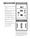
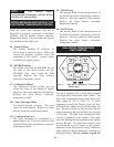
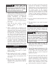
DISPLAY
SETUP OF THE TEMPERATURE
CONTROLLER