


32 | en LTC 8600 | LTC 8800 Series
Bosch Security Systems, Inc. Instruction Manual F.01U.127.393 | 2.0 | 2009.03
8.6.1 LTC 8600 Series or LTC 8800 Series Video Input Terminations
Each VIM card for an LTC 8600 Series or an LTC 8800 Series system has DIP
switches for selecting the termination of each individual video line. To terminate an
input line, make sure that the appropriate DIP switch on the VIM card is ON. If non-
terminated operation is required for looping purposes, turn the switch OFF (Switch
1 corresponds to the first video input channel of the card).
If looping video inputs are desired, the LTC 8600 Series and the LTC 8800 Series
systems may utilize the LTC 8808/00 Video Interconnect Panel. Both bays provide
video looping connections which interface to the LTC 8808/00 using coax type rib-
bon cables supplied with the patch panel. Each LTC 8808/00 provides looping capa-
bility for up to 32 video inputs.
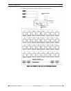
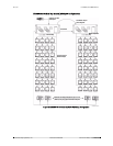
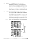
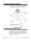
8.6.2 LTC 8802 Series Monitor Expansion Bay Video Input Connections
If an LTC 8802 Series monitor expansion bay is supplied, each video input signal
that is connected to the LTC 8801 Series main CPU bay must also be connected to
the same numbered input on the monitor expansion bay.
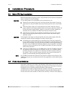
With the LTC 8802 Series monitor expansion bay, ribbon cable connectors are pro-
vided for the video inputs. Video is to be looped from the main bay into the expan-
sion bay through 16 LTC 8809/00 ribbon cables. Connect all LTC 8809/00 ribbon
cables from the appropriate “VIDEO” ribbon cable connector on the main bay to the
corresponding “VIDEO” ribbon cable connector on the monitor expansion bay. The
ribbon cable connectors contain a small “key” protrusion formed into one side of
the connector to assure proper placement into the mating connectors. Be careful
not to force the cables into the mating connectors backwards.
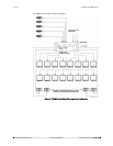
IMPORTANT The Termination DIP switches on the VIM cards installed in the main bay must be
turned OFF. This will make the main bay inputs non-terminated, and the expansion
bay will provide the termination for the video inputs.
Figure 9: Typical LTC 8809/00 Cable Connections
KEYBOARD
VIDEO IN
1
3
5
7
2
4
6
8
CONSOLE
ALARM
PRINTER
SDA
COMM PORT 1
COMM PORT 2
1
3
VIDEO
OUT
2
4
9
1011
12
17
1819
20
25
26
2728
33
3435
36
41
4243
44
49
5051
52
57
58
60
65
66
6768
73
7475
76
81
8283
84
89
90
92
93
94
96
85
8687
88
77
7879
80
69
70
7172
61
62
64
53
5455
56
45
4647
48
37
3839
40
29
30
3132
21
2223
24
13
1415
16
5
6
78
1
SYNC
32 25 18 6
7
8
9
10
11
122431
2330
2229
2128
20
27
19
26
5
4
3
2
17
16
15
14
13
LOOP 1-16
LOOP 17-32
LOOP 33-48
LOOP 49-64
LOOP 65-80
LOOP 81-96
INPUT 97-112
LOOP 97-112
INPUT 113-128
LOOP 113-128
INPUT 129-144
LOOP 129-144
INPUT 145-160
LOOP 145-160
LOOP 241-256
INPUT 241-256
INPUT 225-240
LOOP 225-240
LOOP 209-224
INPUT 209-224
LOOP 193-208
INPUT 193-208
LOOP 177-192
INPUT 177-192
LOOP 161-176
INPUT 161-176
59
9195
63
KEYBOARD
VIDEO IN
1
3
5
7
2
4
6
8
CONSOLE
COMM PORT 2
1
3
VIDEO
OUT
2
4
9
1011
12
17
1819
20
25
26
2728
33
3435
36
41
4243
44
49
5051
52
57
58
60
65
66
6768
73
7475
76
81
8283
84
89
90
92
93
94
96
85
8687
88
77
7879
80
69
70
7172
61
62
64
53
5455
56
45
4647
48
37
3839
40
29
30
3132
21
2223
24
13
1415
16
5
6
78
1
SYNC
32 25 18 6
7
8
9
10
11
122431
2330
2229
2128
20
27
19
26
5
4
3
2
17
16
15
14
13
LOOP 1-16
LOOP 17-32
LOOP 33-48
LOOP 49-64
LOOP 65-80
LOOP 81-96
INPUT 97-112
LOOP 97-112
INPUT 113-128
LOOP 113-128
INPUT 129-144
LOOP 129-144
INPUT 145-160
LOOP 145-160
LOOP 241-256
INPUT 241-256
INPUT 225-240
LOOP 225-240
LOOP 209-224
INPUT 209-224
LOOP 193-208
INPUT 193-208
LOOP 177-192
INPUT 177-192
LOOP 161-176
INPUT 161-176
59
9195
63
LTC 8801
LTC 8802
LTC 8809/00
COM