


F220 Series Detectors with F220-B6/C/E/R Bases Install the Bases | en 17
Bosch Security Systems, Inc. Installation Manual 4998138694 -04 | 2007.01
3.6 Wire Power Supervision Modules
3.6.1 Wire F220-B6E Power Supervision Base
Refer to Section 3.5.2 F220-B6E: for F220-B6E wiring
instructions.
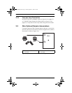
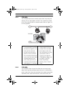
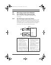
3.6.2 Wire D275 Power Supervision Module
When a D275 Module (refer to Figure 3.6) is used with 12 VDC
systems, connect the red wire to the output terminal (b1) on
the last base in the run. The yellow wire remains unconnected.
For 24 VDC systems, connect the yellow wire to the output
terminal (b1). The red wire remains unconnected.
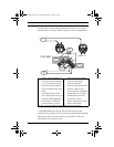
1. EOL resistor (refer to the
control panel’s
installation instructions
for specifications).
2. The positive (+) and
negative (-) IDC wires
(blue) from the D275.
3. Connect the positive (+)
IDC wire through the EOL
resistor to Terminal 2 and
the negative (-) IDC wire
to Terminal 1 on the last
base on the loop.
4. Red wire to Terminal b1
on last base on loop for
12 VDC systems.
5. Yellow wire to Terminal b1
on last base on loop for
24 VDC systems.
6. Black wire (common) to
Terminal a1/a2 on last
base on loop.
7. Power loop: Use either red
or yellow wire; not both.
Fig. 3.6 Wiring a D275 Power Supervision Module as a Loop Terminator
4
7
1
2
2
3
6
5
Common (-)
+24 VDC
+12 VDC
D275
4998138694Er7.book Page 17 Thursday, March 1, 2007 8:42 AM