


RAID Subsystem DVA-16K | Installation Manual Subsystem Monitoring | en 29
Bosch Security System F.01U.027.799 | V2 | 2008.08
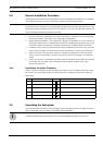
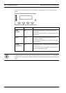
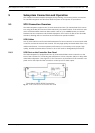
4.2.5 LAN Port LEDs
A shielded Ethernet cable must be used to connect the RJ-45 Ethernet port to a hub on a net-
work after you assign a permanent IP to the RAID subsystem. This enables you to manage your
subsystem via the web. Two (2) LEDs located on the Ethernet port indicate the Ethernet con-
nection status. See Figure 4.4 for the locations of the two (2) LED indicators. Refer to
Table 4.5 for the LED definitions.
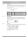
Fig. 4.4 LAN Indicators
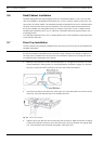
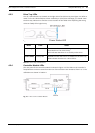
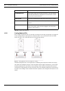
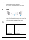
4.2.6 BBU Module LED
The BBU has an LED on the right side of the rear panel. (See Figure 4.5) The function is the
same as the fifth LED on the controller module. The LED is off when the BBU is functioning
normally and is able to sustain the cache memory. The LED flashes to indicate the BBU is
charging. If the LED is illuminating amber, please re-charge the BBU or contact your system
vendor to verify the problem.
Fig. 4.5 BBU Module LED
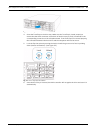
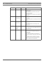
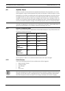
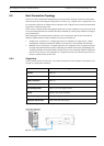
4.2.7 PSU LEDs
Each PSU comes with a single LED at the back (see Figure 4.6), located just above the power
switch that turns on the subsystem. This LED indicates the operational status of the PSU mod-
ule. Please refer to the PSU LED definitions shown in Table 4.6.
Fig. 4.6 PSU Module LED
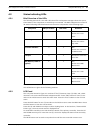
Name Color Status
Online Status Green ON indicates currently connected to a LAN
LAN Activity Green BLINKING indicates active transmission
Table 4.5 LAN Port LEDs Definitions