


Page 66 P/N: F01U035325-01 Copyright © 2007 Bosch Security Systems, Inc. DS7400Xi (4+) Reference Guide
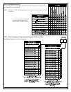
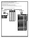
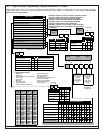
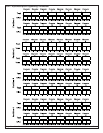
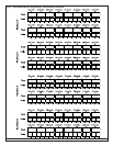
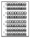
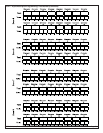
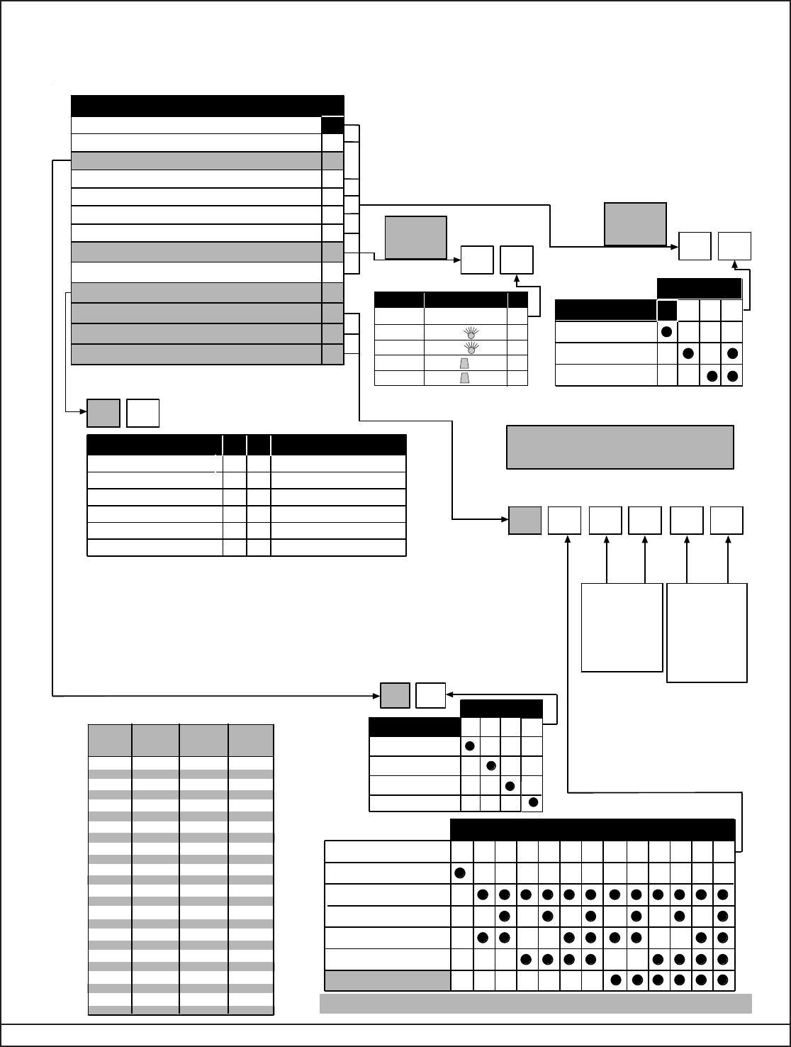
10.37 Output Function Programming: Program Addresses (2772-2843)
Output programming allows you to have the Outputs follow status events by partition or system-wide, or follow zone outputs in an Input/
Output Cross Matrix. See the Programming Addresses Worksheet (P/N: 43850) for a description of each address. See Glossary
(section 6.4) for further details.
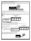
Data Digit 1 Option *2 is used to program an Output
Function to follow status events system-wide.
Data Digit 1 Options *3-*5 are used to program an Output
Function to follow a zone or two zones in an Input/Output
Cross Matrix.
Data Digit
12
Program
Address
1
** = This is only for DS7465 Outputs. DS7488 Outputs will not latch when this is selected.
1
0 2 3 4 5
When panel is not Armed
When panel is Armed
When Zone is opened
When zone is shorted
Activate:
Disabled
6
Enter Data Digit as a:
8
7 9 *0 *1 *2
Latch when activated**
Access output (10 sec. pulse)
Latch ON after Zone Alarm
7
8
9
ON during Entry Pre-Alert
ON when system is armed
Zone alarm
Zone Alarm delayed by 20 sec.
Keypad Sounder output
1
3
6
Panic/Duress output**
*1
0
DDSelect Option
Follow a single zone
Follow System Status Event
Follow two zones-When EITHER zone changes state
Follow two zones-When BOTH zones change state
*2
*3
*4
*5
*0
Keyfob output
Data Digit 1 Options 1-9 and *1 are used to program an Output
Function to follow status events for individual partitions.
Data Digit 1 Option *0 is used to program an Output
Function to follow the Wireless Keyfob Output Buttons.
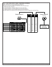
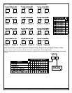
Data Digit
12
Program
Address
1
Enter the
Zone Number
of Second
Zone to
Follow
(see Zone
HEX Values
chart)
Program
Address
1
Program
Address
2
Program
Address
3
2
Data Digit
Data Digit
12
Data Digit
12
Data Digit
12
1
Not Required
if following a
single zone
Enter the
Zone Number
of First Zone
to Follow
(see Zone
HEX Values
chart)
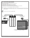
Zone Trouble
Supervisory
Select Option
DDDD
Select Option
1
Communication Failure
Keypad Supervision Fault
Multiplex Bus Fault
Radio Receiver Fault
3
4
5
6
7
8
9
Duress PIN
*1
*0
*2
Low Battery
AC Power Failure
2 Aux Power Fault
Fire Trouble
*0 - *2 are Hex values. They will display as A - C at the keypads.
*0-*5 are Hex values. They will
display as A-F at the keypads.
System Fault**
Disabled
Moment
Moment
0
2
1
3
4
Option
RF3334
Option Key
Option Key
Toggle
Toggle
DD
Follows
Disabled
1 2 3
Burglar Alarm
Fire Alarm
Data Digit
0
14
15
16
17
18
19
20
21
22
23
24
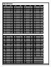
2817
2820
2823
2826
2829
2832
2835
2838
2841
2811
2814
2818
2821
2824
2827
2830
2833
2836
2839
2842
2812
2815
2819
2822
2825
2828
2831
2834
2837
2840
2843
2813
2816
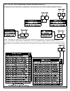
Output
Function
Number
Program
Address
Program
Address
Program
Address
1
2
3
4
5
6
7
8
9
10
11
12
13
2772
2775
2778
2781
2784
2787
2790
2793
2796
2799
2802
2805
2808
2773
2776
2779
2782
2785
2788
2791
2794
2797
2800
2803
2806
2809
2774
2777
2780
2783
2876
2789
2792
2795
2798
2801
2804
2807
2810
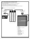
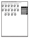
Data Digit
12
*2
Follows
Disabled
0
1
2
Armed Any
Armed Partial
Data Digit
3
Armed Full
Data Digit
12
3
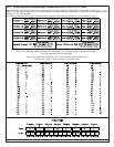
• Serial Transmit fault
• Serial Receive fault
• Aux. Relay fault
• DS7416i Communications fault
•RF Receiver Tamper
•RF Receiver Jammed
• RF Receiver Trouble
• Printer Off-line
**System Faults include:
• RAM fault
• ROM fault
• Bell/Line Monitor fault (DS7420i)
• Line 1 fault
• Line 2 fault
• Bell fault
• Aux. Power fault
• Octal Relay fault
• Serial Module fault (DS7412)