


Page 10 P/N: F01U035325-01 Copyright © 2007 Bosch Security Systems, Inc. DS7400Xi (4+) Reference Guide
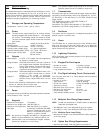
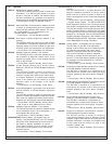
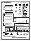
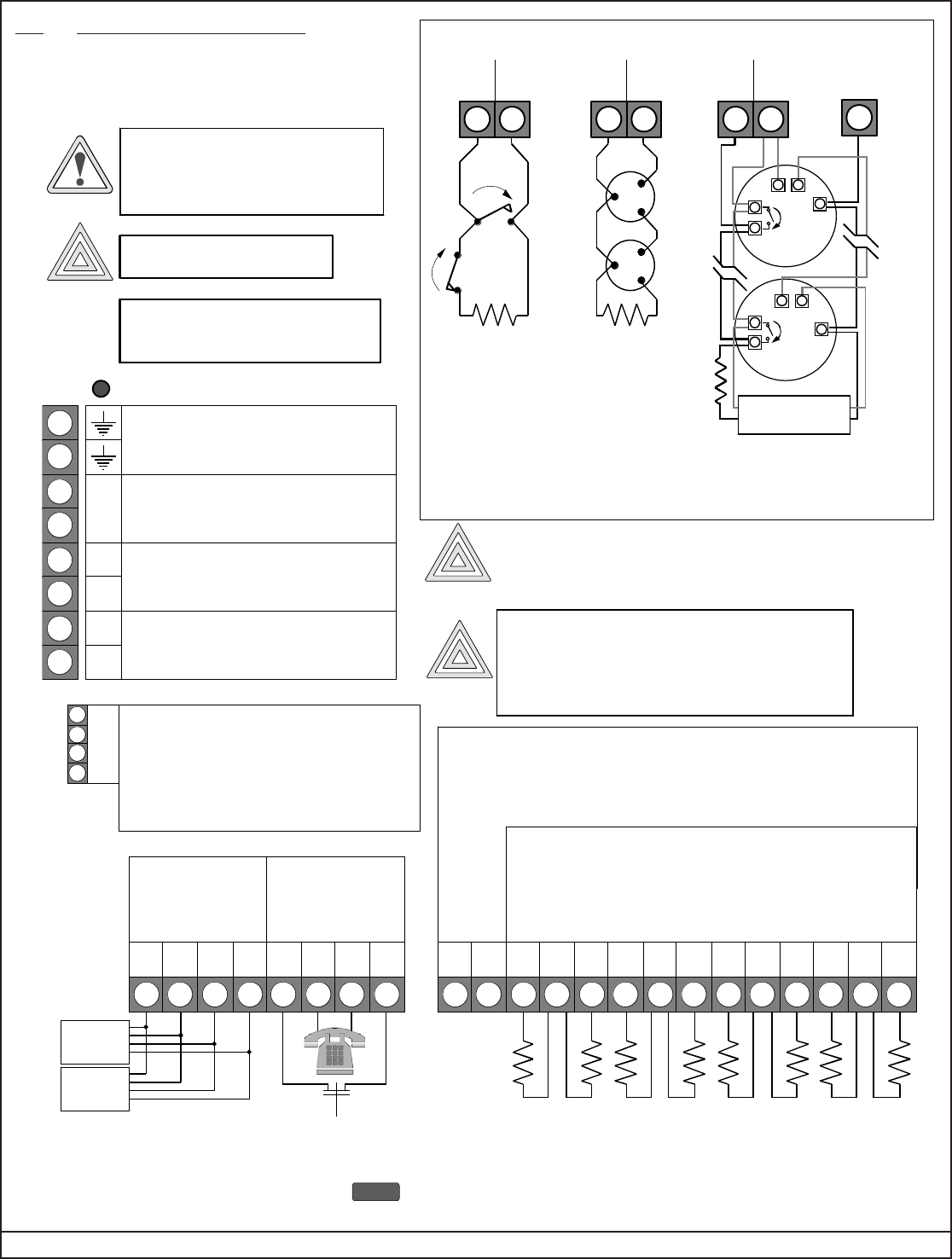
3.0 Control Terminal Wiring
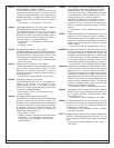
NO
Typical burglar
alarm loop wiring
Z– L+
Typical 2-wire
smoke detector
wiring
Z– L+
Alarm
Power
++
–
Loop +
or PO2
Zone
Input
Aux. Power (—)
(terminal 5 or 7)
–
Alarm
Power
++
–
Typical 4-wire smoke
detector wiring.
For example:
Detection Systems’
DS250 in an MB4W base.
End-of-Line
Supervision Relay
(e.g. Detection Systems’
EOL200)
Z– L+
Loop +Zone
Input
Loop +Zone
Input
in out
in out
NC
TYPICAL BURGLAR AND FIRE WIRING
(for a list of
compatible 2-wire
smoke detectors,
see Technical Service
Note P/N 27685)
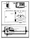
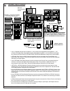
EARTH GROUND:
Must be connected to
a good earth ground such as a cold water
pipe and also connected to the cabinet cover,
using the supplied wire jumper.
ALARM OUTPUT:
Provides 12 VDC, special application, up to
1.75 A for powering bells, siren drivers, etc.
Function programmed in address 2734.
A/C INPUT: Use U. L. listed, 18 VAC 50
VA, class 2 transformer. Model TR-1850
requires 50/60 Hz. unswitched dedicated
outlet - do not share.
1
2
3
4
5
6
7
8
A
C
–
A
–
+
AUXILIARY POWER:
Provides 12 VDC, special application, up to
1.0 A for powering detectors.
A/C Power Indication LED
OPTION BUS:
Used for options such as the DS7416i
Communications Module, the DS7420i Dual
Phone Line Module, etc.
Also for keypads #11 - #15.
For Commercial Fire Mode: Option Bus wiring
should be in conduit if run ouside the
enclosure.
O
P
T
I
O
N
R
B
G
Y
Shared cable is not recommended for keypad,
multiplex, options bus, telephone, or siren wiring.
ZONES 1-8: Zones 1-8 are intended for connection of Normally
Open or Normally Closed alarm contacts. They may also be used
for compatible 2-wire smoke detectors. These zones require a
2.21k
Ω
resistor (P/N 25899) at the end of the loop. Power is
momentarily removed from L+ after a [PIN] + [System Reset] or
during a fire verification.
Zone 1-8 assignments are programmed in address 0031-0038.
17 18 19 20 21 22 23 24 25 26 27 28 29 30
PO1 PO2
1–
L+
2– 3– 5– 6– 7– 8–4–
L+ L+ L+
PROGRAMMABLE OUTPUTS:
PO1 shorts to aux. power negative when activated, PO1 can sink up to 1.0 A.
PO1 function programmed in address 2735.
PO2 supplies 12 V and up to 500 mA when activated.
PO2 function programmed in address 2736.
KEYPAD BUS*:
Up to 15 keypads**
may be used. Can be
“home-run” or
“daisy-chained.”
9 10 1 12 13 14 15 16
RBGYGBSR
Keypad
(#1 - #10)
PHONE LINE:
* = Maximum wire length each: 1000 ft. (305 m).
Maximum wire length total in system: 6000 ft. (1830 m) when using
#22 AWG (0.8 mm) or #18 AWG (1.0 mm) cable.
** = Keypads #1 - #10 connect to the Keypad Bus and keypads #11 - #15
connect to the Option Bus.
TTHRHR
Keypad
(#1 - #10)
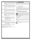
An appropriate two pole disconnect device must be installed
by qualified service personnel, as part of the building installation.
Before servicing, remove all power
including the transformer, battery and
phone line. A complete functional test
is required after any programming.
WARNING
System is Power Limited except for
battery terminals. All wiring entering
this enclosure must be power limited.
Incorrect connections may
result in damage to the unit.
CAUTION
Danger of explosion if battery is incorrectly replaced.
Replace with the same or equivalent type
recommended by the manufacturer.
Dispose of used batteries according to the
manufacturer's instructions.
CAUTION
CAUTION
NOTE