


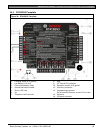
D9412GV3/D7412GV3 | Operation and Installation Guide | Specifications
.
Bosch Security Systems, Inc. | 10/10 | F01U143070-03 74
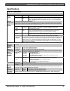
Specifications
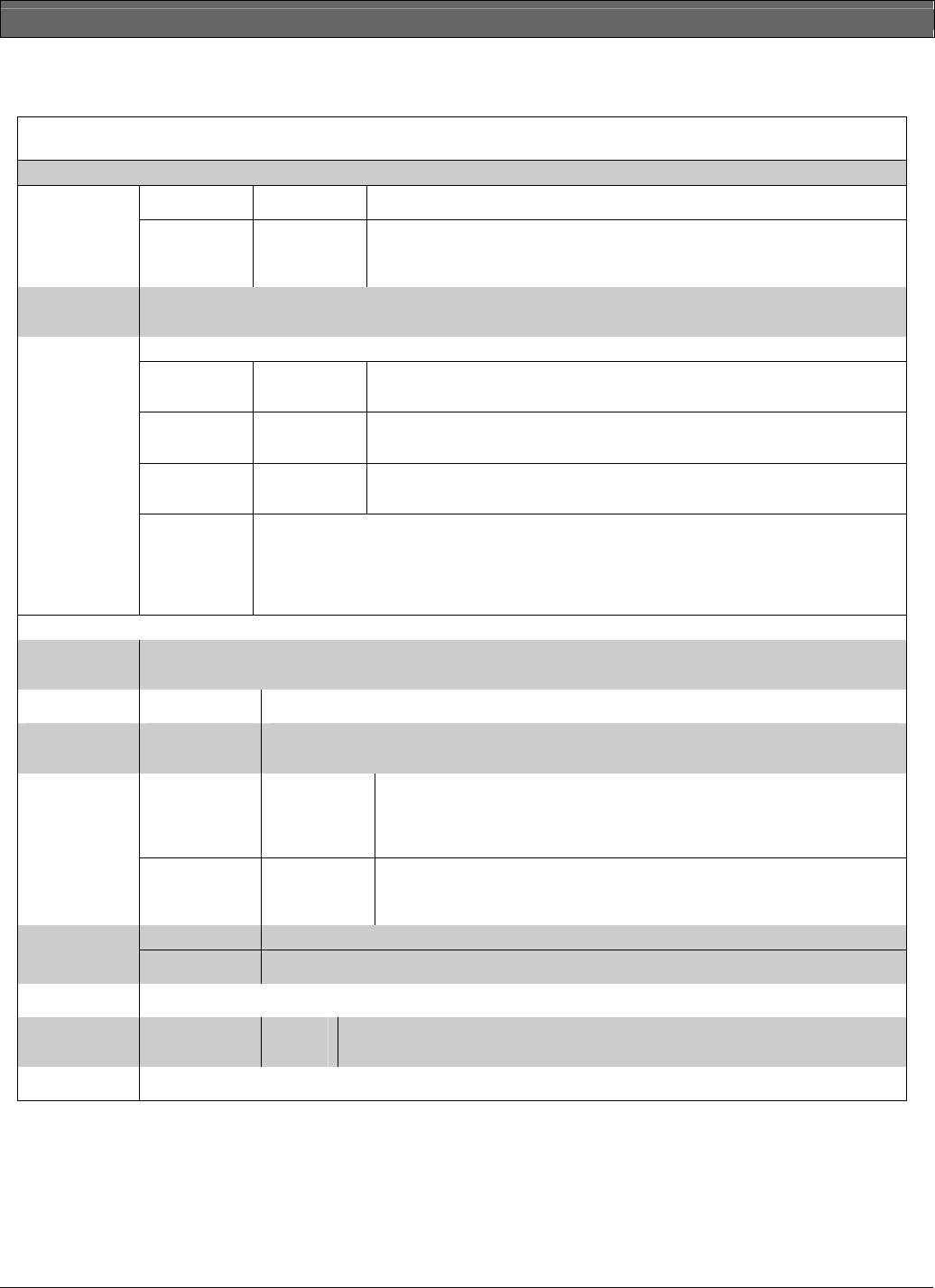
Table 26: Specifications
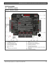
Primary:
Terminals 1
and 2
16.5 VAC 40 VA class 2 plug-in transformer (D1640) Voltage Input
(Power
Supply)
Secondary: Terminals 4
and 5
Sealed lead-acid rechargeable battery (12.0 VDC, 7 Ah or 12.0 VDC, 17.2 or 18
Ah). The control panel supports up to two 12.0 VDC, 7 Ah batteries using the
D122 Dual Battery Harness or two D1218 (12.0 VDC, 17.2 or 18 Ah) batteries
using a D122.
Current
Requirements
Control Panel: Idle 225 mA; Alarm 300 mA
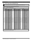
Refer to the Current Rating Chart for Standby Battery Calculations section in the D9412GV3/D7412GV3 Approved
Applications Compliance Guide (P/N: F01U143069) for the current draw requirements of other system components.
All external connections are power-limited except battery terminals.
Continuous
Power
Outputs
Terminals 3,
24, and 32
1.4 A maximum at 12.0 VDC nominal (continuous supply) total for all devices and
outputs supplied at Terminals 3, 24, and 32 and at the accessory and
programming connectors.
Alarm Power
Output
Terminals 6
and 7
2.0 A maximum at 12.0 VDC nominal output. Output can be steady or one of
three pulsed patterns depending on programming. Refer to Relays in the
D9412GV3/D7412GV3 Program Entry Guide (P/N: F01U170807).
Switched Aux
Power
Terminal 8
1.4 A maximum at 12.0 VDC nominal output. Continuous output is interrupted by
Sensor Reset or alarm verification depending on programming. Refer to Relays
in the D9412GV3/D7412GV3 Program Entry Guide (P/N: F01U170807).
Power
Outputs*
Fire and
Fire/Burglary
Systems
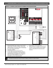
To comply with UL 985 and 864 listing standards for fire alarm systems (effective March 1, 1989),
the total combined continuous and alarm current draw for the system during alarm conditions must
be limited to 1.4 A provided by the primary power supply (rectified AC). If current draw for the
system exceeds 1.4 A, remove connected devices until the current draw falls below 1.4 A. Then,
connect the removed devices to a D8132 Battery Charger Module or to an external power supply
(refer to Figure 29 on page 58).
*For UL 864 applications, refer to Table 3 on page 11 for compatible devices.
Minimum
Operating
Voltage
10.2 VDC
SDI Bus SDI Bus A (+):
SDI Bus B (-):
9 VDC 4572 m (15000 ft) maximum
9 VDC 4572 m (15000 ft) maximum
Telephone
Connections
Connection:
Two Telco
lines:
RJ31X or RJ38X jack can connect the control panels.
Bosch Security Systems, Inc. D928 Dual Phone Line Module required for two phone line service.
Supervision supplied by the control panel.
Discharge
Cycle
13.9 VDC
13.8 VDC
12.1 VDC
10.2 VDC
10.0 VDC
Charging float level.
Charging status LED on.
Low Battery and AC Fail Reports if programmed. Low Battery LED on.
Minimum operational voltage
Battery load shed (processing functions continue if AC is present).
Battery
Discharge/
Recharge
Schedule
Recharge
Cycle
AC ON
13.7 VDC
13.9 VDC
Load shed relay resets, battery charging begins, Battery Trouble and AC
Restoral Reports sent.
Battery Restoral Report sent, Low Battery LED off.
Charging status LED off, battery float charged.
Temperature: 0°C to +50°C (+32°F to +122°F) Environmental
Relative
Humidity:
Maximum 93% non-condensing
Arming
Stations
D720/D720B Keypads, D1255/D1255B/D1255RB Keypads, D1256/D1256RB Fire Keypads; D1257/D1257RB Fire
Alarm Annunciators; D1260/D1260B Keypads; Keyswitch
Point
Thresholds
On-board
Points 1 to 8
Open
Normal
Short
Greater than 3.7 VDC, but less than 5.0 VDC.
Greater than 2.0 VDC, but less than 3.0 VDC.
Greater than 0.0 VDC, but less than 1.3 VDC.
Compatible
Enclosures
D8103 Universal Enclosure, D8109 Fire Enclosure, D8108A Attack Resistant Enclosure, BATB-40 Battery Box