


D9412GV3/D7412GV3 | Operation and Installation Guide | 9.0 Off-Board Points
.
Bosch Security Systems, Inc. | 10/10 | F01U143070-03 45
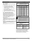
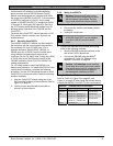
Use the point DIP switches to disable conflicting
points, such as when a D9210B Access Control
Module must be assigned to a point that falls within
the range of the D8128D OctoPOPIT. In this example,
a D9210B is assigned to Point 20. On the same
system, a D8128D OctoPOPIT is assigned to Points
17 through 24. Moving the DIP switch for Point 4 to
the OFF position would effectively disable Point 20,
allowing normal operation of the D9210B and the
OctoPOPIT.
Terminate each OctoPOPIT sensor loop with a 1 kΩ
EOL resistor. Attach a resistor even if you do not
enable the loop.
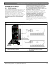
9.4.5 Mounting OctoPOPITs
The D8128D OctoPOPIT Module can be installed in
the enclosure with the control panel using standard
four-conductor 0.8 mm (22 AWG) wire, or in a
separate enclosure (Model D8103, D8103A, or
D8109) up to 61 m (200 ft.) from the control panel
using shielded (recommended) standard four-
conductor 0.8 mm (22 AWG) wire. If using the D125B
or D129, refer to the Specifications section of the
D8128D Installation Guide (P/N: F01U070537) for
cabling requirements.
For UL Listed systems, mount the D8128D in a
tamper-proof enclosure. To install OctoPOPITs in the
control panel’s enclosure, complete the following
procedure. Use the D137 Mounting Bracket to install
OctoPOPITs in enclosures with no module-mounting
locations available.
1. Align the OctoPOPIT module using any of the
four mounting locations in the enclosure. Refer to
Figure 2 on page 15.
2. Use the screws provided with the module to
secure it in the enclosure.
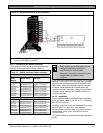
9.4.6 Wiring OctoPOPITs
Warning: Disconnect all power to the
control panel before beginning any work
with the internal components. Serious
injury could result from electrical shock.
1. Power down the control panel:
a. Disconnect the positive (red) battery lead at
the battery.
b. Unplug the transformer.
A D8128D OctoPOPIT can be installed
up to 61 m (200 ft.) from the control
panel.
2. Connect the D8128D to the control panel using
either of the following methods:
Wire the D8128D to the terminal strip on the
side of the POPEX Module, or
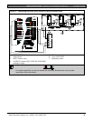
Connect the D8128D using the Molex
®
connectors (P1 and P2). Refer to Using
Molex® Connectors on page 48.
Caution - AC induction: Avoid installing
Zonex data wires and Zonex input (sensor
loop) wires around any AC conduit, wiring,
or electrical devices that emit fields of
electromagnetic interference (EMI).
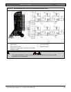
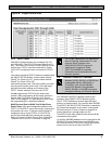
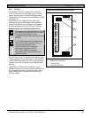
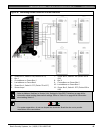
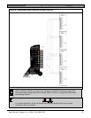
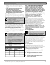
Using the Terminal Strip
Refer to Table 16, Figure 20 on page 46, and
Figure 21 on page 47 when using the terminal strip to
connect the D8128D OctoPOPIT to the control panel.
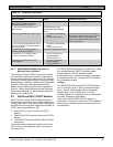
Table 16: Terminal Strip Connections
D8128D D9412GV3 D7412GV3
Common Terminal 23 Terminal 23
Out Zonex 1 = Terminal 27
Zonex 2 = Terminal 25
Terminal 27
In Zonex 1 = Terminal 28
Zonex 2 = Terminal 26
Terminal 28
+12 V Terminal 24 Terminal 24