


D9412GV3/D7412GV3 | Operation and Installation Guide | Appendix A: System Wiring Diagrams, Issue A
.
Bosch Security Systems, Inc. | 10/10 | F01U143070-03 68
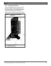
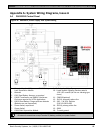
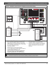
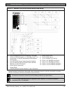
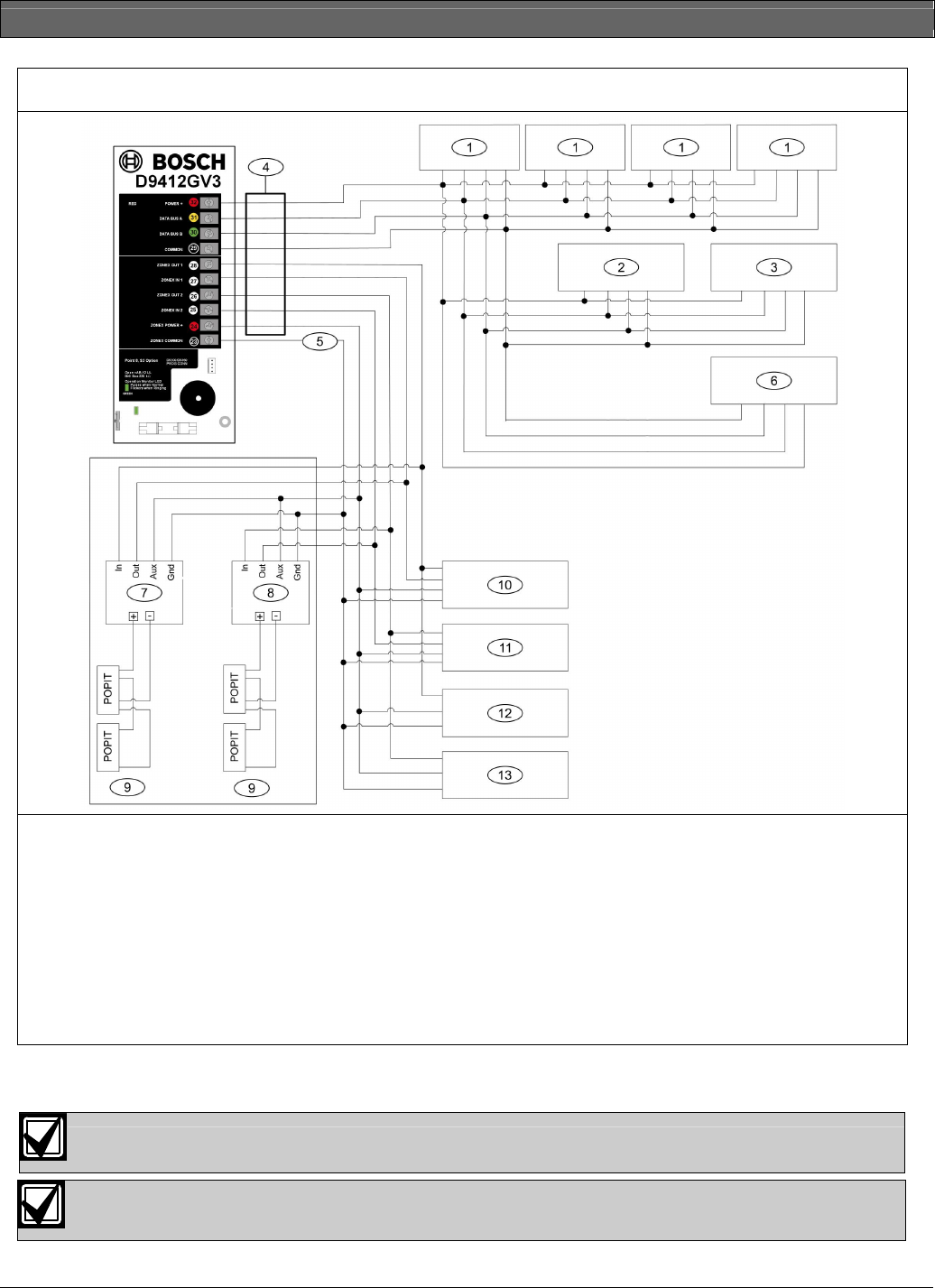
Figure 37: D9412GV3, SDI Devices System Wiring System Wiring
1 - Up to 16 supervised D1255 (all versions), D1255RB,
D1256, D1256RB Keypads, or D1257RB or D1257 Fire
Annunciators, or up to 8 supervised D1260 Keypads
(all versions)
2 - Up to 8 D9210B Access Control Interface Modules
3 - Up to 3 supervised 9131A Parallel Printer Interface
Modules, or other SDI devices
4 - Power limited, supervised
5 - Power limited
6 - DX4020 Network Interface Module or other SDI device
7 - D8125 POPEX No.1
8 - D8125 POPEX No. 2
9- Up to 119 D9127U/T POPITs
10 - Zonex 1: 15 D8128Ds maximum*
11 - Zonex 2: 15 D8128Ds maximum*
12 - Zonex 1: Up to 8 D8129s maximum*
13 - Zonex 2: Up to 8 D8129s maximum*
* The number of D8129 OctoRelays that can be connected to each zonex terminal on the control panel is limited by the number of
D8128D OctoPOPITs connected to the same terminal. Refer to the D8128D Installation Guide (P/N: F01U070537) or the D8129
Operation and Installation Guide (P/N: F01U036302) for specific information.
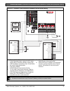
All external connections except Terminal 5 (battery position) are power limited.
Fire and Intrusion devices must be on separate circuits. Refer to ICP-SDI-9114 Installation
Instructions (P/N: F01U030068).