


D9412GV3/D7412GV3 | Operation and Installation Guide | Appendix A: System Wiring Diagrams, Issue A
.
Bosch Security Systems, Inc. | 10/10 | F01U143070-03 69
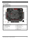
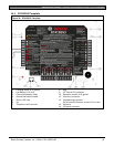
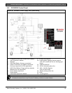
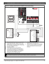
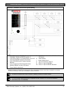
A.2 D7412GV3 Control Panel
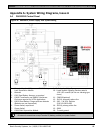
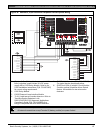
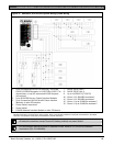
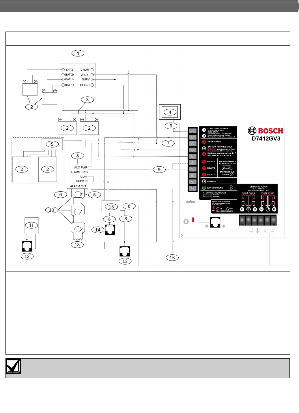
Figure 38: D7412GV3, Power Supply Side System Wiring
1 If required by local AHJ, connect D113 Battery
Lead Supervision Module.
2 Batteries
3 - D122 Dual Battery Harness, as required
4- D1640 Transformer and D8004 Transformer
Enclosure required for NFPA Applications
5 - D8132 Dual Battery Charger with two batteries
(Batteries are not supervised.)
6 - Power limited, supervised
7 - Power limited
8 - D192G Bell Supervision Module
9 - To Relay A or Relay B
10 - Listed Audible Signaling Devices rated at
12.0 VDC nominal (do not use vibrating type
horns)
11 - C900V2 (optional)
12 - RJ31X, secondary phone line
13 - 560 , 2 W EOL Resistor
(P/N: 15-03130-005)
14 - RJ31X, primary phone line
15 - D928
16 - To earth ground
All external connections except Terminal 5 (battery positive) are power limited.