


– 5 –
PLACE THE
WATER
SYSTEM IN
OPERATION
Warning: Handhole
cover may loosen
during shipping –
check for tightness
before putting heater
in operation.
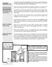
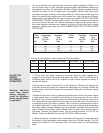
For any horizontal run exceeding the maximum length specified in Figure 4, or
any lift of more than 10 feet, a booster pump must be used. Booster pumps may
b
e obtained from Sun Tec Hydraulics, Rockford, Illinois. Booster pumps must be
installed as close to the oil supply tank as possible. Suction and return lines
should be the same diameter and both go within 6” of the bottom of the tank. The
return line should stop slightly above the suction line. Use a minimum of fittings.
Make bends in the tubing with as large a radius as possible. DO NOT USE COM-
PRESSION FITTINGS. Caution must be used in the final connection to the burner
so as not to strain the fuel unit. Before attaching the tubing to the burner, form a
coil in the tubing to minimize any vibration. Bury the oil lines in the floor for quiet
operation, making sure there are NO CONNECTIONS OR FITTINGS UNDER
THE FLOOR.
1. Fill the tank with water, opening a hot water faucet to allow trapped air to
escape from the heater. Open the cold water inlet valve. Shut off each faucet as
it delivers water that is free of air. Inspect for leaks. Never operate an empty or
partially full heater
.
2. Be sure the oil tank is filled with #1 or #2 heating oil. Remove the transformer
hold down screw and swing the transformer back open on the hinge. Rotate the
blower wheel a few times to loosen the pump shaft. Swing the transformer closed
and fasten.
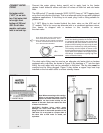
3. Bleed air from the oil line by opening the bleed valve on the fuel pump. Attach
a small plastic tube to the bleed valve fitting on the pump and run to a gallon
container. Turn on the electricity and set the thermostat so the burner motor runs.
The heater will not ignite when the bleed valve is open. Bleed the line until the oil
is completely clear, not milky or opaque. The oil must be transparent and free of
air bubbles and froth. To keep the burner control from locking out while bleeding
the pump, attach a jumper between the flame detector terminals after starting the
burner
. Remove the jumper when finished. Shut the bleed valve and the burner
will ignite. Remove the plastic tubing. Set the pump pressure to 100 PSI for
Wayne, Carlin and Beckett burners and 150 PSI for Riello burners.
4.
Adjust the burner combustion air in accordance with the burner manufacturer’s
instructions. Using combustion instruments, check the C02 and smoke.
The C02
should be at least 10 1/2% minimum with 0-to-trace smoke on the Bacharach
scale.
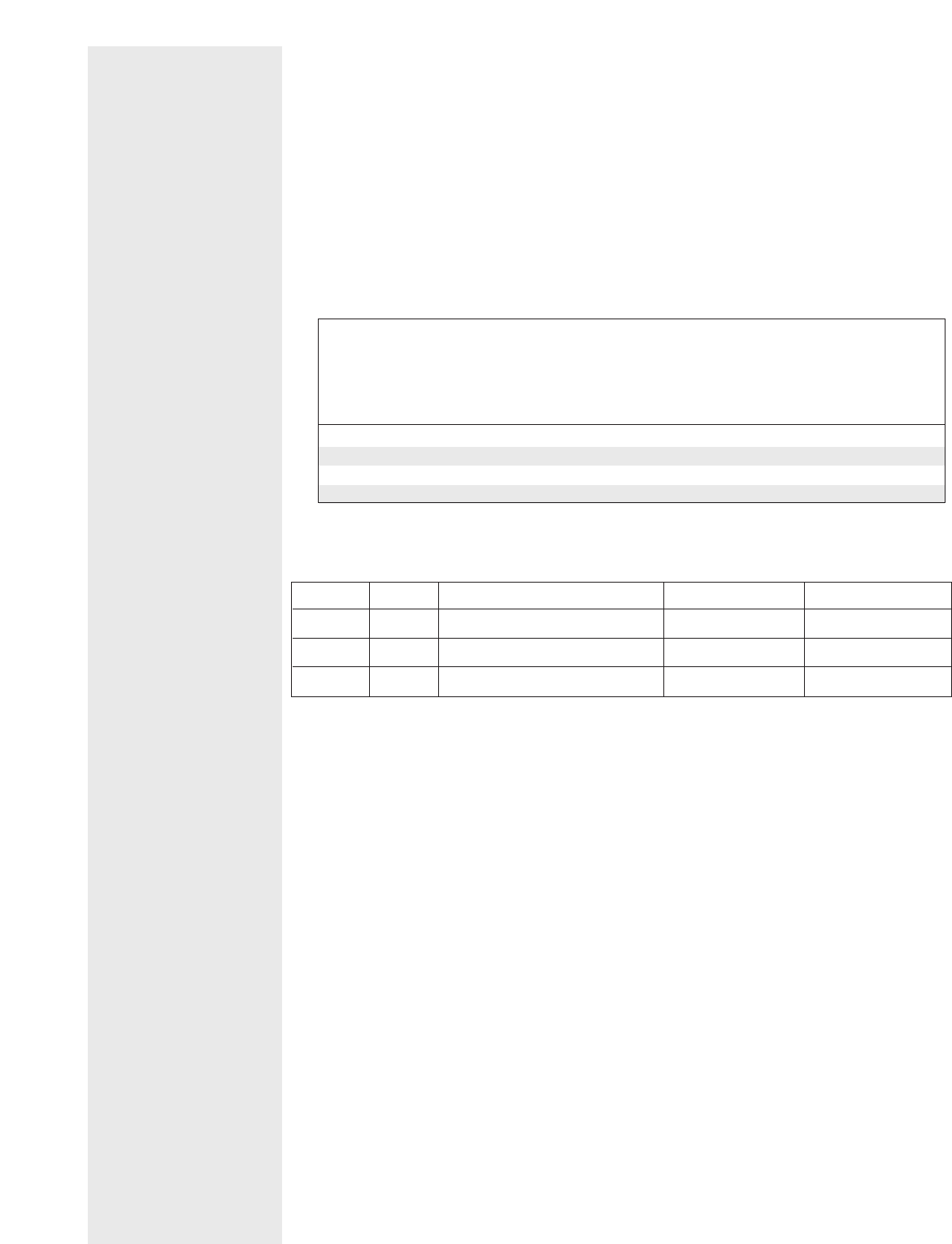
Your log (or one similar to this) must be filled out as follows:
Date Time Test person’s name Set temp.
o
F Outlet temp.
o
F
FIGURE 4: MAXIMUM LIFT & HORIZONTAL RUN
1-Pipe Single Stage Horizontal 2-Pipe Two-Stage Horizontal
System Pump Run System Pump Run
3/8” O.D. 1/2” O.D. 3/8” O.D. 1/2” O.D.
Lift Tube Tube Lift Tube Tube
0’ 65’ 100’ 0’ 75’ 100’
4’
45’ 100’ 4’ 64’ 100’
7’ 31’ 100’ 7’ 55’ 100’
8’ 16’ 64’ 10’ 47’ 100’