


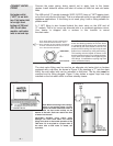
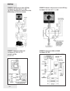

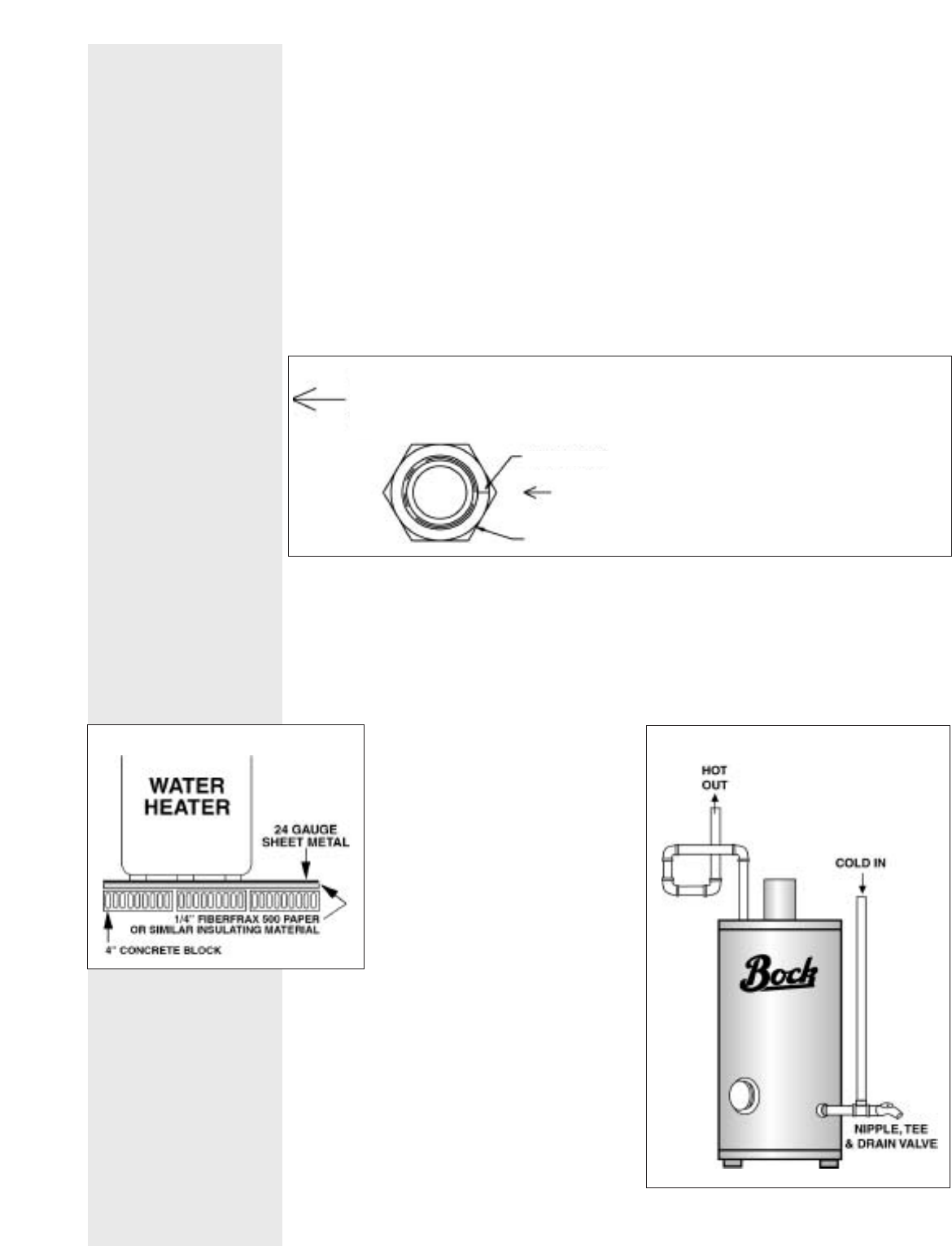
The drain valve fitting may be used as
an alternate cold water inlet on heaters
equipped with a dip tube, as shown in
Figure 3. By plumbing a “T” into the drain
fitting, the cold water inlet can be
relocated to this point. The dip tube
must
be removed and its fitting plugged.
Figure 3 also shows a copper loop heat
trap installed on the hot water outlet to
reduce standby losses.
Note: When converting to this configu-
ration on an existing heater
, visually
inspect the heater and make certain it
does not have scale buildup on the
bottom of the tank. Scale can restrict the flow
of water into the tank.
CAUTION!!
Scalding injury and/or water
damage can occur from either the manual
lifting of the lever or the normal operation of the
T&P
valve if it is not piped to a proper drain. If
the valve fails to flow water or reseat, call
a plumber
.
– 3 –
FIGURE 3
FIGURE 2
CONNECT WATER
PIPING
Hot water outlet
(“HOT”) is on tank
top. Cold water inlet
is on right front
bottom of 33E and
40E. On all other
models, cold water
inlet is on tank top.
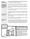
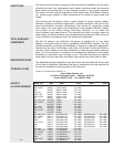
The 33E and 40E models are equipped with a
brass inlet bushing installed in the tank. Heat-
ers
equipped with this bushing are marked next
to the inlet by the decal shown on the left. The
purpose of this bushing is to help keep the tank
bottom free of sediment by aiding tank flushing.
This bushing must be located as shown on the
decal to function properly. Do not allow the bush-
ing to rotate out of position when tightening the
inlet fittings. In installations requiring high flow
rates, contact the factory.
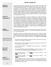
NOTE: INDEX MARK ON INLET BUSING MUST
P
OINT TOWARD ARROW ON DECAL. HOLD
INLET
B
USHING OR NIPPLE WHEN TIGHTENING
FITTINGS. ROTATING BUSHING COULD DRASTI-
C
ALLY REDUCE PERFORMANCE.
INLET BUSHING
INDEX MARK
Connect the water piping, being careful not to apply heat to the heater
nipples. Install dielectric unions and shut off valves on both hot and cold water
l
ines.
The 40E and all “C” models (example: 32EC, 51PPC) have a 1” NPT tapping locat-
ed on the front left side of the tank. This is an alternate outlet for use with combined
appliance applications. If this fitting is not used, plug it with a fitting suitable for
potable water.
A 1” NPT fitting is also located behind the drain valve on the 40E and all
“C” models. This is for use as an alternate inlet or a combined appliance return.
Your heater is shipped with a reducer in this location to mount
the drain valve.
The drain valve fitting may be used as an alternate cold water inlet on heaters
equipped with a dip tube, as shown in Figure 3. By plumbing a “T” into the drain
fitting, the cold water inlet can be relocated to this point. The dip tube
must be
removed and its fitting plugged. Figure 3 also shows a copper loop heat trap
installed on the hot water outlet to reduce standby losses.