


– 4 –
Inspect the incoming water line for check valves or water pressure reducing
v
alves. Any type of check valve may cause pressure to build up in the heater and
cause tank failure. If the heater is installed in a closed system or if backflow pre-
v
enters and pressure regulators are installed, add an expansion tank. Do not try
to heat hard water. Install a water softener if the heater is being used in a hard
water area (water hardness more than 7 grains).
An approved temperature and pressure (T&P) relief valve is factory installed in
the opening provided in the upper right hand side of the heater. Pipe the T&P to
within 6" of the floor or to a floor drain with a free flowing drain pipe. Do not install
a check valve in the cold water line.
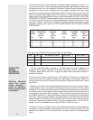
Using “L” or “A” type venting, connect the heater to the chimney. Use the same
size smoke pipe as the heater flue pipe (on models 20e, 20pp, 32E, 32PP and
33E, you may use 4" with a reducer if needed).
WARNING:
On Models 40E, 5OES, 50ESC, 51E, 51EC, 51PP, 51PPC. 71E and
120E, do not reduce the smoke pipe diameter. Run a separate smoke pipe from
the water heater to the chimney wherever possible.
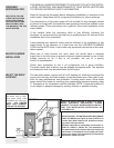
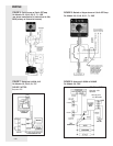
If it is necessary to tee into an existing smoke pipe, be sure the connector being
teed into is large enough to accommodate the products of combustion of all units
attached to it. When teeing into another connector, run in at 45° angle (see Figure
1). Install a draft regulator control only if necessary. Overfire draft should not be
positive. Stack draft should be -.02” W.C. minimum to -.05” W
.C. maximum; CO2
should be a minimum of 11%. If a draft control is installed on the chimney,
another one on the heater is not needed.
The oil burner is equipped with a primary relay
. An aquastat with immersion
well is packed with the burner. The thermostat is factory set at 120°F for residen-
tial use (see caution on page 1 regarding temperature variations). Install the
immersion well with the aquastat and check the bulb length (see “Burner &
Controls” section, page 10).
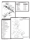
Remove the cardboard core from the burner opening. Mount the burner on stud
bolts and place the gasket (supplied) between the burner flange and the heater.
Secure the burner to the heater with 1/4 -20 nuts (supplied). Open the inspection
door on the heater and check the burner tube with a mirror before firing to
be sure the opening is not blocked (see Maintenance and Service sections on
pages 6 and 7 for troubleshooting).
All wiring must comply with applicable codes and ordinances. The primary relay
is wired to the burner at the factory. Install the aquastat well in the 3/4" tapping at
the front of the heater. Be sure the sensing bulb is inserted all the way into the
well. For Honeywell aquastats, tighten the screw on top of the aquastat to secure
the control to the well. For Carlin EZ-Temp aquastats, refer to the pre-packaged
installation guide for proper set-up procedure. Refer to drawings for correct mod-
els. Connect the power supply to the aquastat and run through a fused discon-
nect switch (attached to heater in field). See Figure 1.
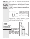
Gravity System: The oil burner is normally equipped with a single-stage pump
equipped for one line (gravity) flow. Use 1/2" O.D. soft copper tubing and attach
with flared fittings. DO NOT
USE COMPRESSION FITTINGS. Install the shut
off valve and oil filter in the oil line. Follow the pump manufacturer’s instructions
(attached to the pump).
Lift System: The burner should be ordered with a 2-stage pump. Run a 2-line
system (suction and return lines). Install the bypass plug according to the
instructions attached to pump (plug is in a bag with an instruction sheet).
CONNECT THE OIL
LINE
WARNING!! WHEN YOU
INSTALL THE BYPASS
PLUG YOU MUST RUN A
TWO-LINE SYSTEM.
CONNECT THE
ELECTRICITY
MOUNT THE OIL
BURNER
CONNECT TO
CHIMNEY