


14
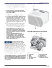
Wire the Burner
Install the burner and all wiring in accordance with the
National Electric Code ANSI/NFPA 70 (Canada CSA
C22.1) and all applicable codes and requirements.
Wire the burner in compliance with all instructions and
diagrams provided by the appliance manufacturer.
Verify operation of all controls in accordance with the
appliance manufacturer’s guidelines.
Sequence of Operation
RM7897C & RM7840L Flame Safeguard Controls
Initiate – The primary control enters the INITIATE
sequence when the control is fi rst powered on or
power returns after an interruption. The initiate
sequence is a ten second delay during which the
control verifi es line voltage stability.
Standby – The control enters STANDBY until the
limits, operating limit control, burner switch, and all
microcomputer-monitored circuits are in the correct
state.
Load Demand – Operating limit control contacts
close on drop in temperature (or pressure) and
initiates the start sequence.
Prepurge – The control will signal the PREPURGE
sequence when the airfl ow interlock and all
switches are in the correct state. The Prepurge
sequence is the amount of time the blower motor
runs prior to the ignition start sequence. Timing
for the Prepurge sequence is determined by a
card mounted inside the control module (typically
30 seconds). For the RM7897A control, Prepurge
is conducted with the air damper in the low fi re
position. For the RM7840 control the air damper
opens to the high fi re position for the timed
prepurge period and returns to the low fi re position
before releasing the control for ignition.
Trial for Ignition (TFI) – After the Prepurge
sequence has timed out, the ignition and main gas
valves will be energized. Because the burner has
direct spark ignition for the main fl ame, the fl ame
must be established and detected by the control
within 4 seconds or lockout will occur.
Flame Stabilization – The burner will operate in
low fi re for 10 seconds before initiating high fi re.
Run – With a fl ame established and the control
1.
2.
3.
4.
5.
6.
7.
Do Not Bypass Safety
Controls
Tampering with, or bypassing safety controls
could lead to equipment malfunction and result in
asphyxiation, explosion or fi re.
Safety controls are designed and installed to provide
protection.
Do NOT tamper with or bypass any safety control.
If a safety control is not functioning properly, shut off
all main electrical power and gas supply to the burner
and call a qualifi ed service agency immediately.
y
y
y
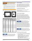
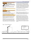
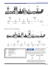
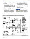
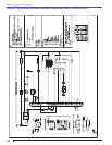
See Figures 9A & 9B for typical
wiring diagrams, with the fl ame
safeguard control, for reference purposes only. Check
the literature that was packaged with the burner for the
primary control manufacturer’s instructions and the exact
wiring diagram for your specifi c burner.
Electrical Shock Hazard
Electrical shock can cause severe personal
injury or death.
Disconnect electrical power before installing or
servicing the burner.
Provide ground wiring to the burner, metal control
enclosures and accessories. (This may also be
required to aid proper control system operation.)
Perform all wiring in compliance with the National
Electrical Code ANSI/NFPA 70 (Canada CSA C22.1)
y
y
y
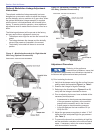
Keep Service Access
Covers Securely Installed
These covers must be securely in place to prevent
electrical shock, damage from external elements,
and protect against injury from moving parts.
All covers or service access plates must be in place
at all times except during maintenance and service.
This applies to all controls, panels, enclosures,
switches, and guards or any component with a cover
as part of its design.
y
y
Incorrect Wiring Will
Result in Improper Control
Operation
Fire or Explosion Hazard
Can cause severe injury, death, or property damage.
The control can malfunction if it gets wet, leading to
accumulation of explosive vapors.
Never install where water can fl ood, drip or
condense on the control.
Never use a control that has been wet - replace it.
y
y
y
Section: Wire the Burner & Sequence of Operation