


Instruction Manual – Model CF2300A Oil Burner
9
Form 6104 BCF-23-R0399
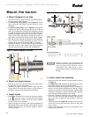
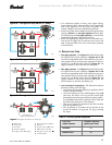
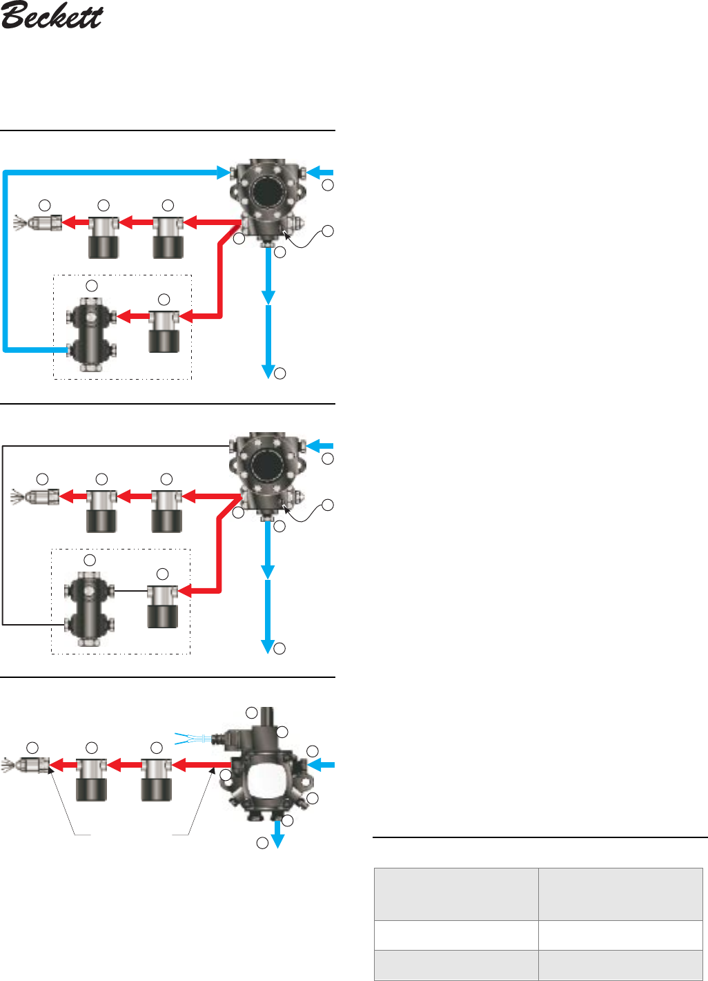
Figure 9a – Two-pipe oil flow, low fire, “H” pump • Use continuous lengths of heavy-wall copper tubing,
routed under the floor where possible. Do not attach fuel
lines to the appliance or to floor joists if possible. This
reduces vibration and noise transmission problems.
• Install an oil filter sized to handle the fuel unit gearset flow
capacity (Table 3) for two-pipe systems. Size the filter
for the firing rate for one-pipe systems. Locate the filter
immediately adjacent to the burner fuel unit.
• Install two high-quality shutoff valves in accessible loca-
tions on the oil supply line. Locate one valve close to the
tank. Locate the other valve close to the burner, upstream
of the fuel filter.
❏ Burner fuel flow
• One-pipe systems – See Figure 8 for the fuel flow paths
for high-fire and low-fire operation. Figures 8a and 8b
are based on type H fuel units, with external by-pass pres-
sure regulator. The low-fire by-pass regulation is done in-
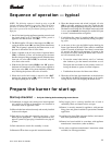
ternally for type B fuel units, shown in Figure 8c. Oil
supply connects to one of the fuel unit Inlet ports.
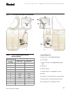
• Two-pipe systems – See Figure 9 for the fuel flow paths
for high-fire and low-fire operation. Figures 9a and 9b
are based on type H fuel units, with external by-pass pres-
sure regulator. The low-fire by-pass regulation is done in-
ternally for type B fuel units, shown in Figure 9c. Oil
supply connects to one of the fuel unit Inlet ports. Oil
return connects to the fuel unit Return port.
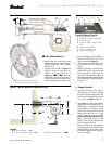
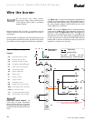
• Low-fire/high-fire operation – The fuel unit nozzle port
pressure is factory set at 300 psig.
• At high fire, full pressure (300 psig) is applied at the oil
nozzle, causing full input.
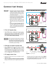
• At low fire, the by-pass valve (item e) opens. For type H
fuel units, this allows oil to by-pass the nozzle path
through the external by-pass pressure regulator (item f).
For type B fuel units, the by-passing is done inside the
fuel unit when the by-pass valve operates.
• The by-pass oil flow is returned to the fuel unit Inlet
port for type H fuel units.
• This by-passing of oil reduces the oil pressure at the
nozzle (to between 125 psig and 175 psig), reducing
the input.
Figure 9c – Two-pipe oil flow with “B” pump
a Return port
b Nozzle port
c Oil valves
d Nozzle & adapter
e By-pass valve (“H”
pump)
f By-pass pressure regulator
g Inlet port
h By-pass valve (“B” pump)
k Return line to oil tank
m One-pipe by-pass loop,
³⁄₈³⁄₈
³⁄₈³⁄₈
³⁄₈"
p Air bleed valve
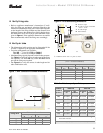
Table 3 – Fuel unit gearset capacities
Figure 9b – Two-pipe oil flow, high fire, “H” pump
Legend (for Figures 8a, 8b, 8c, 9a, 9b and 9c)
Fuel unit
model number
Gearset capacity
(gallons per hour)
B2TA8852 39
H4PAN-C151H 69
300 psig high fire
125 to 175 psig low fire
2323a
d
a
c
c
g
k
f
b
p
h
b
300 psig
d
300 psig
2313b
g
f
a
e
cc
p
k
k
g
f
300 psig
2313a
d
125 psig
to
175 psig
a
e
cc
b
p