


Instruction Manual – Model AFG Oil Burner
6
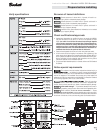
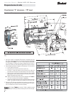
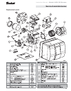
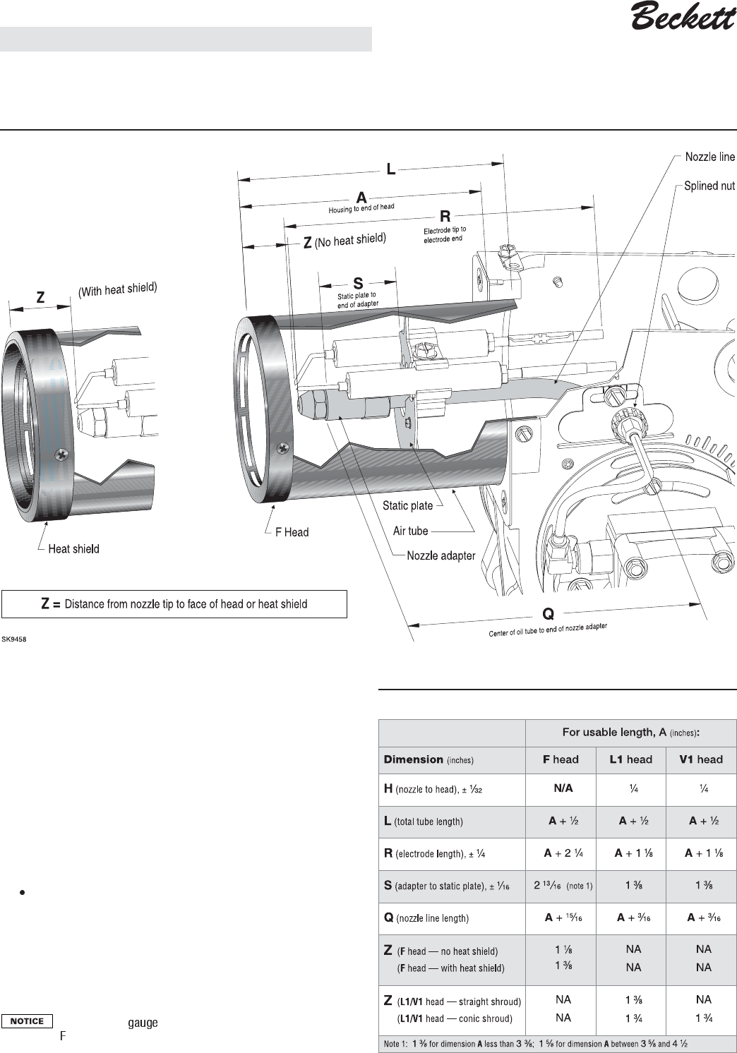
Figure 2 —“F” heads (plus burner detail for all head styles) (see Table 3 for dimensions)
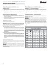
Check/adjust "Z" dimension - "F" head
Prepare burner & site
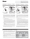
Table 3 — Dimensions for Figures 2, 3 and 4
1. See Figure 2 above. The important "Z" dimension is the distance from the
face of the nozzle to the flat face of the head (or heat shield, if applicable).
This distance for F heads is 1 ¹⁄₈" (1 ³⁄₈" if the air tube has a heat shield).
The "Z" dimension is factory set for burners shipped with the air tube in-
stalled. Even if factory set, verify that the "Z" dimension has not been changed.
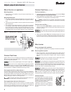
2. Use the following procedure to adjust the "Z" dimension, if it is not correct:
• Turn off power to the burner.
• Disconnect the oil connector tube from the nozzle line.
• See Figure 2. Loosen the splined nut from the nozzle line. Loosen the
hex head screw securing the escutcheon plate to the burner housing.
• Place the end of a ruler at the face of the nozzle and, using a straight
edge across the head, measure the distance to the face of the head. (A
Beckett T500 gauge may also be used.)
Slide the nozzle line forward or back until this dimension for F heads is
1¹⁄₈" (1³⁄₈" to the face of the heat shield, if applicable).
• Tighten the hex head screw to secure the escutcheon plate to the burner
chassis. Then tighten the splined nut and attach the oil connector tube.
3. Recheck the "Z" dimension periodically when servicing to ensure the es-
cutcheon plate has not been moved. You will need to reset the "Z" dimen-
sion if you replace the air tube or nozzle line assembly.
The Beckett Z (part number Z-2000) is available to permit
checking the head "Z" dimension without removing the burner from the appli-
ance.