


D-1.2) Testing Oil:
1. Place pump on it’s side, remove gland nut on cable
(10) and drain oil into a clean, dry container.
2. Check oil for contamination using an oil tester with a
range to 30 kilovolts breakdown.
3. If oil is found to be clean and uncontaminated
(measures above 15 KV. breakdown), refill the motor
housing as per section D-1.3.
4. If oil is found to be dirty or contaminated (or measures
below 15KV. breakdown), then the pump must be
carefully inspected for leaks at the shaft seal (19),
cord inlet (10), and lower end bell (15) before refilling
with oil.
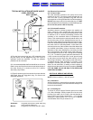
D-1.3 Replacing Oil in Motor Housing:
Drain all oil from motor housing and dispose of properly.
Refill with new cooling oil as per table 1. An air space of
approximately 15% by volume must remain in the top of
the motor housing to compensate for air expansion. Set
unit upright and fill only until the windings, as viewed
through the control cable hole, are covered.
WARNING ! - DO NOT overfill oil overfilling of
motor housing with oil can create excessive
and dangerous hydraulic pressure which can destroy
the pump and create a hazard. Overfilling oil voids
warranty.
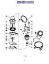
D-2) Bottom Plate:
Remove screws (24), and remove bottom plate (23) from
body (17). Clean and examine impeller (19). If impeller
vanes are clogged, or it is excessively worn or broken, the
impeller should be replaced. Follow procedures in
Paragraph D-3 for replacing impeller.
D-3) Impeller:
After removing the bottom plate (23), as outlined in
Paragraph D-2, the impeller (19), may be removed by
removing set screw (21), and lockwasher (20), and turning
impeller counterclockwise to remove from shaft. When
reassembling the impeller (19), turn the impeller clockwise
until it touches built-in wear plate, then back it off 3/4 of a
turn for proper clearance.
Hold impeller firmly and replace lockwasher (20), and set
screw (21). Replace bottom plate (23) and screws (24).
Pump impeller clearance can be adjusted by loosing set
screw (21) and turning impeller clockwise for less
clearance or counterclockwise for more clearance.
Re-tighten set screw (21) and turn the impeller by hand to
check for free rotation. It is important that impeller
clearance be as close to top plate as possible without
interference for best performance.
D-4) Motor and Bearing Service:
If stator (8) needs replaced, first drain oil per Paragraphs
D-1.1 through D-1.3, then remove slotted head cap screws
(5) from the upper motor cap (4) and lift the motor cap (4)
off carefully as grounding wire (25) is attached to the inside
of the motor cap. Remove the ground screw (6) and set
motor cap (4) to one side.
Remove bottom plate per Paragraph D-2 and impeller (19)
per Paragraph D-3. Remove snap ring (12) and shim (28)
from shaft. Press or tap the rotor and shaft assembly (8)
out with a plastic or rawhide hammer. Note that the lower
bushing will not come out with the shaft and rotor
assembly. Now remove the seal (15) by inserting a
screwdriver into lower motor housing (14) and tapping
lightly with a hammer.
Push the new rotor and shaft assembly (8) into the
housing. Coat stationary (15) with a thin oil coating and
use a plastic pusher to install the seal (15) into housing
(14). DO NOT use any sharp instruments that may
damage the seal. DO NOT chip, scratch or mar the carbon
face. Press the ceramic seal in place with the rubber ring
facing the impeller. Install the stator and fasten ground
wire inside the motor cap (4) and tuck wires up into
housing to prevent rubbing on the rotor. Insert square ring
(13) into lower motor housing (14) and replace motor cap
(4) making sure not to damage square ring. Insert screws
(5) and tighten. Re-fill motor housing per Paragraph D-1.3.
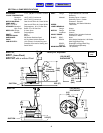
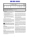
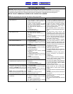
MODEL HP VOLT PH RPM NEMA FULL LOCKED CORD CORD CORD WINDING
NO. (Nom) START LOAD ROTOR SIZE TYPE OD RESISTANCE
CODE AMPS AMPS OHMS
BP27 1/3 115 1 1550 E 9.9 15.5 16/3 SJTW-A 0.360 2.00/2.35
BP27A 1/3 115 1 1550 E 9.9 15.5 16/3 SJTW-A 0.360 2.00/2.35
BP27D 1/3 115 1 1550 E 9.9 15.5 16/3 SJTW-A 0.360 2.00/2.35
BP27HT 1/3 115 1 1550 E 9.9 15.5 16/3 SJTW-A 0.360 2.00/2.35
Winding Resistance ± 5%
Pump rated for operation at ± 10% voltage at motor.
Mercury Switch on BP27A, Cable 16/2, SJOW-A, 0.320 O.D., Piggy-Back Plug.
Diaphragm Switch (BP27D), Cable 18/3, SJT, 0.360 O.D.
7
Manual Index
HOME
MENU