


4) Plug the level control plug into a GFI receptacle, then
plug the pump into the piggyback plug. One cycle of
operation should be observed , so that any potential
problems can be corrected.
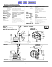
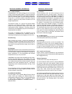
5) It is recommended that the float should be set to insure
that the sump well liquid level never drops below the top of
the motor housing or a minimum level of 2.5" (64mm)
above the pump bottom.
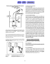
6.) Figure 3 shows a typical connection for pumps with the
wide angle float and piggy-back plug. for manual and
automatic operations.
Automatic- Plug float cord into GFI outlet, then plug
pump cord into float cord.
Manual- Plug pump cord directly into GFI outlet.
C-4) Electrical Connections:
C-4.1) Power Cable:
The cord assembly mounted to the pump must not be
modified in any way. This pump comes complete with a 3
wire cord and 3 prong grounded plug that must be
connected into a 3 wire grounded Ground Fault receptacle.
DO NOT remove ground pin from electrical plug. It is NOT
recommended to use an extension cord with these pumps.
Do not use the power cable to lift pump.
C-4.2) Overload Protection:
Automatic thermal overload protects the sealed-in-oil
motor, running dry may overheat the motor and trip the
overload. The type of in-winding overload protector used
is referred to as an inherent overheating protector and
operates on the combined effect of temperature and
current. This means that the overload protector will trip out
and shut the pump off if the windings become too hot, or
the load current passing through them becomes too high.
It will then automatically reset and start the pump up after
the motor cools to a safe temperature. In the event of an
overload, the source of this condition should be determined
and rectified immediately. Using a ohmmeter, check the
resistance of the motor windings by connecting one lead
clip to each electric "flat" prong on the power cord plug.
The ohmmeter should be on R x 1 setting. Normal reading
is 1.7/1.9 . To check for ground, place the ohmmeter on R
x 100k, connect one lead clip to the "round" ground prong
on the power cord and touch the other lead clip to each
"flat" prong individually. If the reading is other than infinity,
a leakage through stator insulation or moisture in the
windings is occurring and the stator must be removed,
dried out and rechecked. A reading at zero indicates a
dead short and the stator will have to be replaced. DO NOT
LET THE PUMP CYCLE OR RUN IF AN OVERLOAD
CONDITION OCCURS !
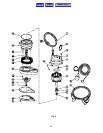
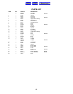
SECTION D: SERVICE AND REPAIR
NOTE: All item numbers ( ) refer to Figure 4.
D-1) Lubrication:
Anytime the pump is removed from operation, the cooling
oil in the motor housing (5) must be checked visually for oil
level and contamination.
D-1.1) Checking Oil:
To check oil, set unit upright. Remove gland nut on cable
(10). With a flashlight, visually inspect the oil in the motor
housing (5) to make sure it is clean, clear and that the oil
level is above all internal componentry . If oil appears
satisfactory, replace gland nut. If oil is low or appears
contaminated, test oil as per section D-1.2
WALL SOCKET
GFI
DISCHARGE ⇒
⇒ INFLOW
TYPICAL INSTALLATION WITH WIDE ANGLE
LEVEL CONTROL
ON
OFF
Fig. 2
Automatic
Manual
Fig. 3
6
Manual Index
HOME
MENU