


SECTION B: GENERAL INFORMATION
B-1) To the Purchaser:
Congratulations! You are the owner of one of the finest
pumps on the market today. Barnes
®
Pumps are products
engineered and manufactured of high quality components.
Over one hundred years of pump building experience
along with a continuing quality assurance program
combine to produce a pump which will stand up to the
toughest applications.
This Barnes Pumps, Inc. manual will provide helpful
information concerning installation, maintenance, and
proper service guidelines. Check local codes and
requirements before installation. Servicing should be
performed by knowledgeable pump service contractors or
authorized service stations.
The pump is packaged ready for installation and no
connections or adjustments are necessary except for
attaching discharge piping and plugging in service cord.
B-2) Receiving
Upon receiving the pump, it should be inspected for
damage or shortages. If damage has occurred, file a claim
immediately with the company that delivered the pump. If
the manual is removed from the crating, do not lose or
misplace.
B-3) Storage:
Short Term- Barnes Pumps are manufactured for efficient
performance following long inoperative periods in storage.
For best results, pumps can be retained in storage, as
factory assembled, in a dry atmosphere with constant
temperatures for up to six (6) months.
Long Term- Any length of time exceeding six (6) months,
but not more than twenty four (24) months. The units
should be stored in a temperature controlled area, a roofed
over walled enclosure that provides protection from the
elements (rain, snow, wind blown dust, etc..), and whose
temperature can be maintained between +40 deg. F and
+120 deg. F.
Pump should be stored in its original shipping container
and on initial start up, rotate impeller by hand to assure
seal and impeller rotate freely.
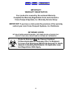
B-4) SERVICE CENTERS:
For the location of the nearest Barnes Pumps Service
Center, check your catalog, your Barnes Pumps, Inc.
representative or Barnes Pumps, Inc. Service Department
in Piqua, Ohio, telephone (937) 77808947 or Crane
Pumps & Systems Canada Inc., in Bramton, Ontario
(905) 457-6223.
SECTION C: INSTALLATION
C-1) Location:
These pumping units are self-contained and are
recommended for use in a sump or basin. This pump is
designed to pump rain water or light effluent, nonexplosive
and noncorrosive liquids and shall NOT be installed in
locations classified as hazardous in accordance with the
National Electrical Code (NEC), ANSI/NFPA 70 or the
Canadian Electrical Code (CEC). The sump or basin shall
be vented in accordance with local plumbing codes.
Provide proper sump diameter of approx. 18" (457mm)
minimum and depth of approx. 20" (508mm) minimum to
allow the pump and switch to operate without restriction.
The float switch should not come in contact with side or
bottom of sump. Make sure sump is free of string, cloth,
nails, gravel, etc. before installing pump. Never install the
pump in a trench, ditch, or hole with a dirt bottom where
the suction will become plugged.
C-1.1) Submergence:
The minimum sump liquid level should never be less than
2.5 inches (64mm) above the pump bottom.
C-2) Discharge:
Discharge piping should be as short as possible. The
installation of a check valve in the discharge piping is
recommended for each pump being used. The check valve
is used to prevent backflow into the sump. Excessive
backflow can cause flooding and/or damage to the pump.
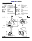
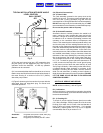
C-3) Liquid Level Controls
Figure 2 shows a typical installation for any submersible
pump using a level control mounted to the discharge piping
with a piggy-back plug.
General Comments:
1) Never work in the sump with the power on.
2) Level controls are factory set for a pumping differential
of 9 inches. If that is the cycle desired, simply circle the
discharge pipe with the pipe mounting strap, feed the end
through the worm drive, and tighten with a screwdriver. Be
certain that the level control cannot hang up or foul in it’s
swing. Also, make certain the pump impeller is still
submerged when the level control is in the ’off’ mode.
3) If a higher pump differential is needed, grip the cord near
the neck of the float, then using the other hand, exert a
steady force on the lower edge of the cable clamp. The
cable clamp should slide up to the new pivot point. Attach
the level control to the discharge pipe in the manner
described above.
5
Manual Index
HOME
MENU