


Manual 2100-538E
Page 4 of 23
WALL MOUNT GENERAL INFORMATION
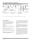
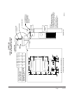
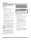
Environmental Control Unit (ECU) Wall-Mount Model Nomenclature
SHIPPING DAMAGE
Upon receipt of equipment, the carton should be
checked for external signs of shipping damage. If
damage is found, the receiving party must contact the
last carrier immediately, preferably in writing,
requesting inspection by the carrier’s agent.
GENERAL
The equipment covered in this manual is to be installed
by trained, experienced service and installation
technicians.
The refrigerant system is completely assembled and
charged. All internal wiring is complete.
The unit is designed for use with or without duct work.
Flanges are provided for attaching the supply and return
ducts.
These instructions explain the recommended method to
install the air cooled self-contained unit and the
electrical wiring connections to the unit.
These instructions and any instructions packaged with
any separate equipment required to make up the entire
air conditioning system should be carefully read before
beginning the installation. Note particularly “Starting
Procedure” and any tags and/or labels attached to the
equipment.
While these instructions are intended as a general
recommended guide, they do not supersede any national
and/or local codes in any way. Authorities having
jurisdiction should be consulted before the installation is
made. See Page 3 for information on codes and
standards.
Size of unit for a proposed installation should be based
on heat loss calculation made according to methods of
Air Conditioning Contractors of America (ACCA). The
air duct should be installed in accordance with the
Standards of the National Fire Protection Association
for the Installation of Air Conditioning and Ventilating
Systems of Other Than Residence Type, NFPA No.
90A, and Residence Type Warm Air Heating and Air
Conditioning Systems, NFPA No. 90B. Where local
regulations are at a variance with instructions, installer
should adhere to local codes.
NOTE: Vent options X and B are without exhaust capability. May require separate field supplied barometric relief in building.
KW
Electric
Heat @
Rated
Voltage
MODEL
SERIES
Wall-Mount
OTHER OPTIONS
X - None
ELECTRICAL RATING
R - 230/208-60-1 & 220/200-50-1
S - 230/208-60-3 & 220/200-50-3
T - 460-60-3 & 400-50-3
REVISIONS
VENTILATION OPTIONS
X - Barometric Fresh Air Damper (Standard)
B - Blank-off Plate
FILTER OPTIONS
X - One Inch Throwaway (Standard)
W - One Inch Washable
P - Two Inch Pleated
COLOR OPTIONS
X - Beige (Standard)
1-White
4 - Buckeye Gray
5 - Desert Brown
6 - Dark Bronze
A - Aluminum
S - Stainless Steel
COIL OPTIONS
X - Standard Copper Tube/Aluminum Fin
1 - Phenolic Coated Indoor Coil
2 - Phenolic Coated Outdoor Coil
3 - Phenolic Coated Indoor & Outdoor Coil
OUTLET OPTIONS
X - Front (Standard)
NOMINAL TONS
3 - 3 Ton (37,000 on 60Hz; 33,700 on 50Hz)
5 - 5 Ton (54,000 on 60Hz; 49,200 on 50Hz)
6 - 6 Ton (68,000 on 60Hz; 61,900 on 50Hz)
COMPRESSOR &
CONTROLS LOCATION
R - Right Side
L - Left Side
SYSTEM DESIGN
Variable Capacity
(Digital Compressor) ECU
W 3 R V 1–R 10 X X X X X X
SPECIAL
FEATURES