


Manual 2100-538E
Page 13 of 23
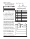
WIRING – MAIN POWER
These units are rated for 60/50 Hz operation as follows.
NOTE: This system must be controlled only by the Bard
8403-064 Digital Thermostat/Controller that is
supplied with the unit. See below for Wiring and
Pages 16-17 for Operating Sequences.
DIGITAL THERMOSTAT/CONTROLLER
Refer to the unit rating plate for wire sizing information
and maximum fuse or “HACR” type circuit breaker
size. Each outdoor unit is marked with a “Minimum
Circuit Ampacity”. This means that the field wiring
used must be sized to carry that amount of current.
Depending on the installed KW of electric heat, there
may be two field power circuits required. If this is the
case, the unit serial plate will so indicate. All models
are suitable only for connection with copper wire. Each
unit and/or wiring diagram will be marked “Use Copper
Conductors Only”. These instructions must be adhered
to. Refer to the National Electrical Code (NEC) for
complete current carrying capacity data on the various
insulation grades of wiring material. All wiring must
conform to NEC and all local codes.
The electrical data lists fuse and wire sizes (75° C
copper) for all models including the most commonly used
heater sizes. Also shown are the number of field power
circuits required for the various models with heaters.
The unit rating plate lists a “Maximum Time Delay
Relay Fuse” or “HACR” type circuit breaker that is to
be used with the equipment. The correct size must be
used for proper circuit protection and also to assure that
there will be no nuisance tripping due to the momentary
high starting current of the compressor motor.
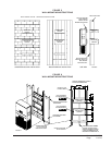
The disconnect access door on this unit may be locked
to prevent unauthorized access to the disconnect. To
convert for the locking capability, bend the tab located
in the bottom left-hand corner of the disconnect opening
under the disconnect access panel straight out. This tab
will now line up with the slot in the door. When shut, a
padlock may be placed through the hole in the tab
preventing entry.
See “Start Up” section for important information on
three phase scroll compressor start ups.
See Table 3 for Electrical Specifications.
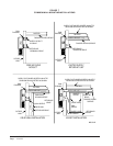
WIRING – LOW VOLTAGE WIRING
230/208V, 1 phase and 3 phase equipment dual primary
voltage transformers. All equipment leaves the factory
wired on 240V tap. For 208V operation, reconnect from
240V to 208V tap. The acceptable operating voltage
range for the 240 and 208V taps are:
TAP RANGE
240 253 – 216
208 220 – 187
NOTE: The voltage should be measured at the field power
connection point in the unit and while the unit is
operating at full load (maximum amperage
operating condition).
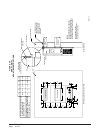
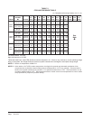
C
5
3
1
6
4
R
7
BLOCK
F
E
Y1
G
W1
W2
Y
UNIT LOW
VOLTAGE
TERMINAL
2
IN3
IN4
-A
+B
24V
24 COM
IN2
GND
OUT 9
GND 7-9
OUT 8
OUT 7
RLY 6
SC 4-6
RLY 5
RLY 4
RLY 3
SC 1-3
RLY 2
RLY 1
MIS-2852 C
8403-066 DIGITAL
CONTROLLER
lanimreTnoitcnuFepyTmroF
B+)desuton(+PTSMsnoitacinummoC
A-)desuton(-PTSMsnoitacinummoC
4NIrosneSerutarepmeTroodtuOtupnI3epyTMHOK01
3NIrecudsnarTerusserPtupnIGISP007-0,CDV5-0
DNGsdnuorGrosneStupnI
2NImralAtuokcoLtupnIerusolCyaleR
MOC42moCCAV42rewoP
V42CAV42rewoP
9TUOlortnoCrotoMnaFtuptuOgolanACDV01-0
9-7DNGdnuorGlortnoCtuptuOgolanA
8TUOlortnoCdioneloSredaolnUtuptuOgolanAMWPCDV5ro0
7TUOlortnoCrotoMrewolBtuptuOgolanACDV01-0
4YLR1#rotcatnoCretaeHtuptuOyaleRyaleR
6-4CS6-4stuptuOyaleRotCAV42rewoP
5YLR2#rotcatnoCretaeHtuptuOyaleRyaleR
6YLR)desuton(
3YLR)desuton(
3-1CS3-1stuptuOyaleRotCAV42rewoP
2YLRrotcatnoCrosserpmoCtuptuOyaleRyaleR
1YLR)desuton(
lacirtcelE
edoC
stloV
zH
esahP
gnitarepO
egatloV
egnaR
R-
1-06-802/032
1-05-002/022
352-791
242-081
S-
3-06-802/032
3-05-002/022
352-791
242-081
T-
3-06-064
3-05-004
605-414
044-063