


Manual 2100-538E
Page 17 of 23
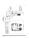
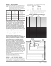
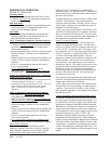
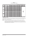
lortnoC
eciveDlamroNlamronbA
roodnI
rotoM
rewolB
lortnoC
draoB
DELdeRtil DELneerG,
trohsdnagnolsehsalf
dellacsinaFnehwsehsalf
otlangiSmorfcdV01-2,rof
.PnosirepmuJ.nommoC
neerGondna,DELdeRoN
sicdV01-2nehwsehsalf
otlangiSmorftneserp
.PnosirepmuJ.nommoC
roodtuO
rotoM
naF
lortnoC
draoB
gnolneerG.tiltonDELdeR
-2nehwsehsalftrohsdna
langiSmorftneserpcdV01
.draobnonommoCot
.PnosirepmuJ
neerGondna,tilDELdeR
sicdV01-2nehwsehsalf
otlangiSmorftneserp
.PnosirepmuJ.nommoC
cdV5
rewoP
ylppuS
caV42nehwtilDELdeR
tatneserpcdV5.tneserp
kcalBdilosdnadeRdilos
.flaHnosrepmujhtoB.seriw
.esufV052A3
toncdV5.tiltonDELdeR
dnadeRdilostatneserp
.seriwkcalBdilos
.flaHnosrepmujhtoB
.esufA3kcehC
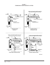
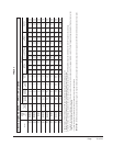
COOLING SEQUENCE
Compressor Operation
The cooling capacity of the WV series is controlled by
loading or unloading the compressor. On a call for
cooling, the unloader solenoid is energized for one
second to ensure pressure equalization in the
compressor. The compressor contactor, RLY 2, is then
energized and the compressor will start. A PI control
loop then calculates the compressor capacity needed to
reach set point and modulates the compressor .
Modulation range is from 20% to 100% capacity.
Modulation is accomplished by a pulse width modulated
signal from OUT 8 which energizes the solid state relay
(SSR) and energizes or de-energizes the unloader
solenoid. The required compressor capacity is
calculated every 15 seconds.
20% load means 0 VDC for 3.0 seconds and 5 VDC for
12.0 seconds from OUT 8.
30% load means 0 VDC for 4.5 seconds and 5 VDC for
10.5 seconds from OUT 8.
40% load means 0 VDC for 6.0 seconds and 5 VDC for
9.0 seconds from OUT 8.
50% load means 0 VDC for 7.5 seconds and 5 VDC for
7.5 seconds from OUT 8.
60% load means 0 VDC for 9.0 seconds and 5 VDC for
6.0 seconds from OUT 8.
70% load means 0 VDC for 10.5 seconds and 5 VDC
for 4.5 seconds from OUT 8.
80% load means 0 VDC for 12.0 seconds and 5 VDC
for 3.0 seconds from OUT 8.
90% load means 0 VDC for 13.5 seconds and 5 VDC
for 1.5 seconds from OUT 8.
100% load means 0 VDC for 15 seconds and 5 VDC for
0.0 seconds from OUT 8.
Outdoor Temperature Sensor
A sensor probe projects out the bottom of the ECU
control box into the outdoor section, and this provides
input for the outdoor fan sequences below 55F and
above 115F described under Outdoor Fan Motor
Operation.
Discharge Temperature Sensor
This sensor is mounted on the compressor discharge line
and protects the compressor against overheating. It
opens at 250F and closes at 200F.
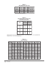
HEATING SEQUENCE
On a call for heating, if the space temperature falls 1°F
below setpoint, the first stage of heating, RLY 4, will
cycle ON. If the space temperature falls 3°F below
setpoint, the second stage of heating, RLY 5, will cycle
ON. Indoor Blower airflow is maintained at the Rated
unit airflow at all times during heating.
LEAD/LAG SEQUENCE
The digital controllers can be used for dual units used in
a redundant application by using the scheduling function
as follows:
1. The controllers should be mounted side by side so
that they are in the same temperature zone.
2. The time setting on both controllers need to be
synchronized to the same time of day. NOTE: there
is a 72-hour time retention if power is removed. If
power off-time exceeds 72 hours, the time clock in
each device must be reset to match. The exact time
is not important as long as both controllers are set
the same unless it is critical to control the time of
day when the units swap operating positions.
3. Set one controller #1 to be Occupied for a 12-hour
period and Unoccupied for the other 12-hour period.
Set controller #2 so that it is exactly the opposite.
Unoccupied for the 12-hour period when #1 is
Occupied and Occupied when #1 is Unoccupied.
4. Set Occupied cooling setpoint the same for each
controller, and Unoccupied the same for each. 4°F
difference is suggested.
5. Set controllers to “Auto” mode of operation.
Example:
1. Both Unit #1 and #2 have Occupied setpoint of
74°F and Unoccupied setpoint of 78°F
2.
Unit #1 set for Occupied from 1:00 a.m. to 1:00
p.m. & Unoccupied from 1:00 p.m. to 1:00 a.m.
3.
Unit #2 set for Unoccupied from 1:00 a.m. to
1:00 p.m. & Occupied from 1:00 p.m. to 1:00 a.m.
4. Every 12 hours the units will swap position as
being the lead unit, and the lag unit is available
for back up operation at the higher temperature
should the situation ever arise.