


8 P/N 118000 rev. A
Banner Engineering Corp. • Minneapolis, MN U.S.A.
www.bannerengineering.com • Tel: 763.544.3164
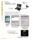
Software Setup
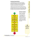
Use the Main Menu toolbar to navigate the PresencePLUS P4 options. Proceeding from left to
right, the buttons in the Menu toolbar step through the process of creating an inspection file.
Inspection Work Flow
step 6
step 6
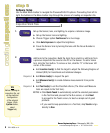
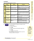
Add tools to the inspection. Build the tools from scratch or add tools from
a previous inspection file saved on the PC or the Sensor. To add a Vision
tool, click the Tool button. To remove a tool, click the “X” in the lower left
corner of the screen.
a. Add Location tool(s) to find the target to adjust the following Regions of
Interest (ROI) for transitional and rotational changes.
b. Add Vision tool(s) to inspect the part.
c. Add Measure tool(s) to create distance measurements from points
found.
d. Add Test tool(s) to set the Pass/Fail criteria. (The Vision and Measure
tools are inputs to the Test tool.)
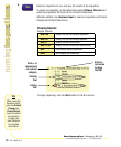
NOTES: • Click Quick Teach to automatically set all the selected parameters
in the Test tool and proceed to the Run screen, or click Next
to proceed to the Teach screen, to teach a sample set of good
products.
• If you want to keep parameters in a Test tool, skip Teach and go
directly to Run.
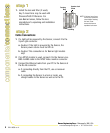
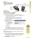
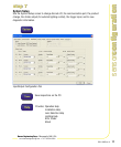
Set up the Sensor, lens, and lighting, to acquire a reference image.
a. Set up the Sensor lens and lighting.
b. Choose Trigger option Continuous for a live image.
c. Click Auto Exposure to adjust the brightness.
d. Focus the Sensor lens by turning the lens until the Focus Number is
maximized.
Required
Required
1.
2.
creating
inspections
creating
inspections
TIPS
Before creating an
inspection file, set
up the electrical
configuration
of the external
trigger. (Click
System button,
select
Trigger tab.)