


4 P/N 118000 rev. A
Banner Engineering Corp. • Minneapolis, MN U.S.A.
www.bannerengineering.com • Tel: 763.544.3164
components/
connections
components/
connections
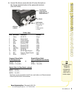
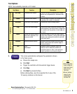
Cable Connections
1. If a light will be powered by the Sensor, connect it to the
3-pin Light connector.
a. Caution: If the light is powered by the Sensor, the
Sensor power source must be 24V dc.
b. Caution: This connection is for Banner light models
only!
2. If an NTSC monitor is used, connect it to the Sensor via a
BNC-to-BNC cable to the NTSC Video monitor connector.
3. Connect the Ethernet cable from your PC to the Sensor at
the RJ-45 connector.
a. If connecting directly from the PC, use a crossover
cable.
b. If connecting the Sensor to a hub or router, use
straight cables to the Sensor as well as to the PC.
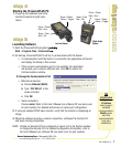
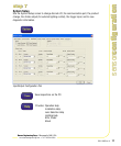
step 1
step 1
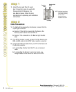
1. Install the lens and filter (if used).
Any C-mount lens may be used with
PresencePLUS P4 Sensors. For
non-Banner lenses, follow the lens
manufacturer’s unpacking and installation
instructions.
step 2
step 2
Focusing
Ring
Aperture Lock
Screw
Focus
Lock Ring
NOTE: If the lens has a focus
lock screw, loosen the
screw before focusing
the lens. Some
lenses also have an
aperature lock screw.