


Instruction 3015-4256 19
Viewing the Fault Log
From the Data Display screen, use the Keypad buttons to place the arrow (>) on the display next to the
FAULTS function. Then press ENTER to display the fault log.
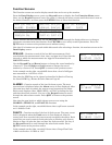
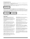
Immediately after selecting the FAULTS function, the most recent fault event is displayed. The fault log
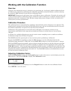
identifies the type of fault, plus the date and time it occurred. In the example below, record #03 shows that
a Zone Flow Fault (fault code <0800>) occurred on 11/12/03 at 08:17.
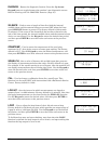
The cause of the fault is identified by a numeric fault code. To convert the fault code into a text
description of the fault, first press the ENTER button and then use the Keypad buttons to scroll through
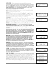
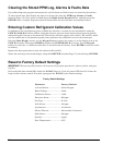
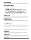
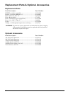
the display until the text description of the fault appears. If the fault code is a combination of two or more
faults, then continue to use the Keypad buttons until all fault text descriptions have been displayed. For
example, the fault code <1800> represents the combination of both a Zone Flow <0800> and a Purge Flow
<1000> fault as shown below:
Note that the Fault Log can be cleared as described in Section Clearing the Stored PPM Log, Alarms &
Faults Data on Page 20.
Fault Codes
<0001> Box Temperature Fault: Enclosure
temperature is outside normal range (or IR
detector has failed). Check that the monitor is not
being subjected to extreme temperatures. Verify
that the ventilation holes are not obstructed. Use
the DIAGNOS function to check the Box
Temperature.
<0002> Bench Temperature Fault: Optical
bench is outside normal operating range (or IR
detector has failed). Check that the monitor is not
being subjected to extreme temperatures.
<0004> - Manifold Pressure Fault: The manifold
pressure is outside normal operating range (or IR
detector has failed). Enter the DIAGNOS function
and record ALL data. Call the factory with this
information for further instructions.
<0010> Loop Fault: The 4–20 mA current loop is
open, or there is a high resistance in the circuit. Check
the wiring to the load/monitoring circuit. If this
feature is not being used, a 100 ohm resistor must be
connected to the 4–20 mA connector (Page 11).
<0100> Zero Filter Fault: A purge filter failure
has occurred. Replace the unit’s charcoal filter.
<0200> Gain Set Fault: The digipot autotune
sequence has failed. This fault will only occur on
first boot up or after a firmware upgrade. Call the
factory for further instructions.
<0400> A/D Fault: A fault has occurred in the
analog-to-digital circuitry. Contact the factory with
this information for further instructions.
<0800> Zone Flow Fault: Check for: A kink in
the gas-sample line or exhaust line; a blocked line-
end filter; a failed pump.
<1000> Purge Flow Fault: Check that the
internal charcoal filter inlet (Page 8) is not blocked.
Once the blockage has been cleared, the monitor
will return to normal operation after the monitor
completes a purge cycle.
<4000> Zero Fault: The IR detector’s output
voltage is out of tolerance. Enter the DIAGNOS
function and record ALL data. Call the factory with
this information for further instructions.
<8000> Clipping Fault: The detector voltage may
be out of tolerance. Use the DIAGNOS function to
check the IR detector voltage. Call the factory with
this information for further instructions.
FAULT CODES ARE ADDITIVE. For example:
A fault code of <1800> indicates that both a Purge
Flow Fault <1000> and a Zone Flow Fault <0800>
have occurred.
#03 <0800> @
11/12/03 08:17
F
AULT CODE<1800>
12 ZONE FLOW
F
AULT CODE<1800>
13 PURGE FLOW