


AXIS Q7401 Video Encoder
Technical Specifications
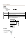
Connectors
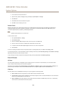
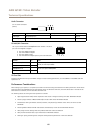
I/O Connector
6–pin terminal block for:
• Auxiliary power (DC output)
• Digital Input
• Digital Output
• 0 V DC (-)
1 2 3 4 5 6
Function Pin Notes
Specications
0 V DC (-)
1
0 V DC
DC output
2
Can be used to power auxiliary equipment.
Note: This pin can only be used as power out.
12 V DC
Max load = 125 mA
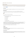
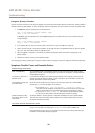
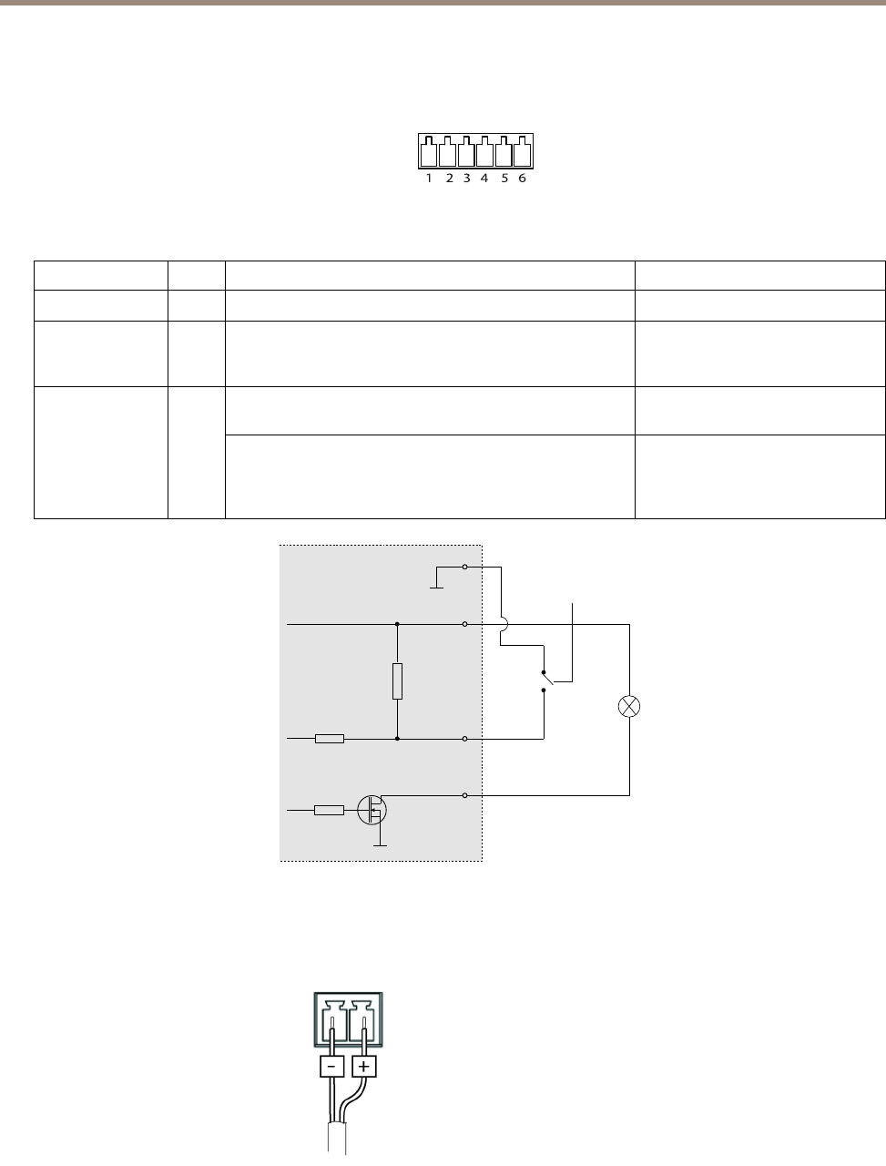
Digital input – Connect to pin 1 to activate, or leave oating
(unconnected) to deactivate.
0 to max 30 V DCCongurable
(Input or Output)
3–6
Digital output – Connected to pin 1 when activated, oating
(unconnected) when deactivated. If used with an inductive
load, e.g. a relay, a diode must be connected in parallel with
the load, for protection against voltage transients.
0 to max 30 V DC, open drain,
100 mA
1
2
E.g. push button
3
4
12 V
max 125 mA
D
S
G
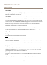
Power Connector
2-pin terminal block for power input.
Use a Safety Extra Low Voltage (SELV)
compliant limited power source (LPS)
with either a rated output power
limited to ≤100 W or a rated output
current limited to ≤5 A.
DC power input
64