


Rev. A.2, 10/03 Page-5
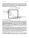
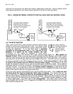
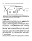
Note installation of the MOV across the power wires to the lock. The MOV is the small black
disk shaped component furnished loose with the DK-26. Its function is to absorb inductive
kickback from the lock’s coil. Without the MOV, this kickback voltage will arc over the relay
contacts and reduce the switching life of the relay. The arc also creates electronic noise which
could occasionally cause the microprocessor to malfunction. The MOV should be spliced into
the lock power wires as close to the lock as possible.
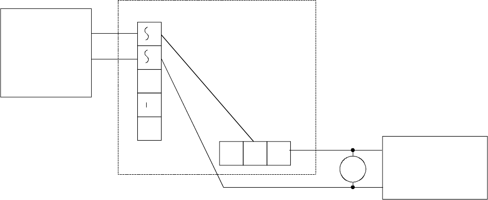
FIG. 3: AC LOCK - AC POWER WIRING
NC1 C1 NO1
AC IN F DC IN /OUT
+
TRANSFORMER
12 OR 24 VAC
AC FAIL SECURE
LOCK
MOV
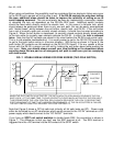
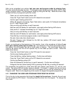
3.3.2 DC LOCK WITH AC POWER
For convenience and economy, most DC electric locks can be operated from an AC transformer
when the DK-26 is used. Select a transformer of the same voltage as the lock (12 or 24). The
CPU board converts the input AC to DC to operate the lock. Make sure the capacity of the
transformer is large enough to operate both the DK-26 and the lock and that the transformer is
UL listed under the UL 294 standard (to maintain the DK-26 UL listed status). The lock must
accept full wave rectified DC power. This is true of most DC locks (including Securitron’s
Magnalocks) but some specialty units require regulated DC power. You must operate those as
described in the next Section. Note finally that many DC lock installations call for battery
backup. To achieve this, you must employ a DC battery backup power supply and also follow
the wiring description in Section 3.3.3.
DC locks come in “fail secure” and “fail safe” versions. A fail secure lock is secure when not
powered and a fail safe lock is secure when powered. All magnetic locks are fail safe. Figure 4
shows AC power being input to the AC terminals. The DC terminals furnish output power for the
lock. DC locks operated in this way must not draw more than 2 Amps. The positive DC
terminal connects to the common of relay #1 and either the NO1 terminal (if the lock is fail
secure) or the NC1 terminal (if the lock is fail safe) connects to the lock’s positive power input.
This is shown in dotted lines. You only connect one of these terminals. Note that some DC
locks are polarized and you must connect lock power correctly to positive and negative. Others
are not polarized and can be connected either way. Consult the lock instructions.
Note installation of the MOV across the power wires to the lock. The MOV is the black disk
shaped component furnished loose with the DK-26. Its function is to absorb inductive kickback
from the lock’s coil. Without the MOV, this kickback voltage will arc over the relay contacts and