


Rev. A.2, 10/03 Page-2
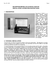
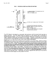
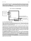
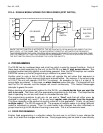
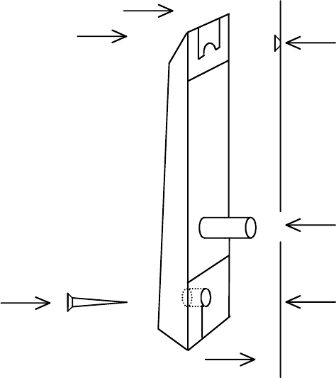
FIG. 1: PHYSICAL INSTALLATION OF KEYPAD
MOUNTING
SURFACE
(1) MOUNT SCREW TO ENGAGE SLOT AT
TOP OF KEYPAD
DRILL 1/8" (3MM) HOLE
(2) DRILL 3/8" (10MM) HOLE FOR CABLE
(3) SECURE BOTTOM WITH SECOND
SCREW. COVER SCREW HEAD WITH
"DK-26" LABEL.
DRILL 1/8" (3MM) HOLE
NOTE: CHOOSE PHILIPS OR SPANNER
(TAMPER) HEAD SCREW
CABLE
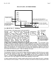
The CPU Board is furnished in a snap-apart steel enclosure with the board itself mounted on
plastic snap-trak. The CPU Board must be installed in a dry location free of extremes of
temperature and humidity. If the 16 ft., twelve conductor cable that is included is not of sufficient
length, additional cabling can be spliced by the installer. However, a long cable run can give
rise to electronic noise problems in certain environments. It should therefore be avoided where
possible and in no case should cable length exceed 100 ft. (30 meters).
Cable entry to the CPU board enclosure can be handled in one of two ways. There is a hole in
the bottom of the enclosure, the use of which creates the most attractive installation as the cable
is completely hidden. Alternately, there is a side knockout in the enclosure cover which permits
surface mounting of the cable. The side knockout also permits a wiring technique which is
convenient when the CPU board enclosure is to be mounted in an awkward location such
as above a drop ceiling. You can pop the board itself out of its snap track and make all your
connections with the board in your hands. The board is then re-snapped into the plastic trak.
The enclosure cover snaps on with the wires emerging from the side knockout. If you use this
technique, avoid touching the components or rear pins on the board as much as possible.
Static electricity can destroy the processor. Also when you snap the board back in its track,
make sure it’s securely done. Sometimes you need to squeeze the outer lips of the track to
insure that the board edges are really seated in the slot.