


Rev. A.2, 10/03 Page-9
When using exit switches, the possibility must be considered that an electronic failure may occur
to the DK-26 and a person will not be able to exit. If the DK-26 controls the only door exiting
the area, additional steps should be taken to improve the reliability of exiting so as to
avoid trapping someone. This can most easily be done by implementing a secondary means
of releasing the lock not dependent on the DK-26's REX input. Additional switch contacts
should be used which directly control the electric lock. In the case of a fail-safe lock, which
should always be employed when there is only one exit path, this can be easily accomplished
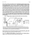
with "double break" wiring between the exit button, electric lock, and DK-26. If the exit button
has a set of normally open and normally closed contacts, it should then be wired according to
Figure 6. When the exit button is depressed, its normally closed contacts directly break power
to the lock while its normally open contacts activate the DK-26. In effect, the lock is released
twice. Note that the NC contacts are placed in the circuit before the DK-26's lock control relay.
This is to aid possible troubleshooting. It is usually easier to get to the DK-26 CPU board than
to get to the push button wiring in a service situation. With wiring as shown in Figure 6, the
push button NC contacts can be metered on the DK-26 CPU board. If for any reason a failure
occurs with the DK-26, a person can still exit by holding the exit button down while pushing the
door open. Note, you should always consult your local building or fire department when
securing doors that are part on an emergency exit path to make sure you are complying
with local codes.
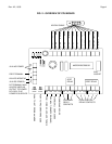
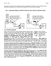
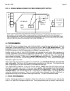
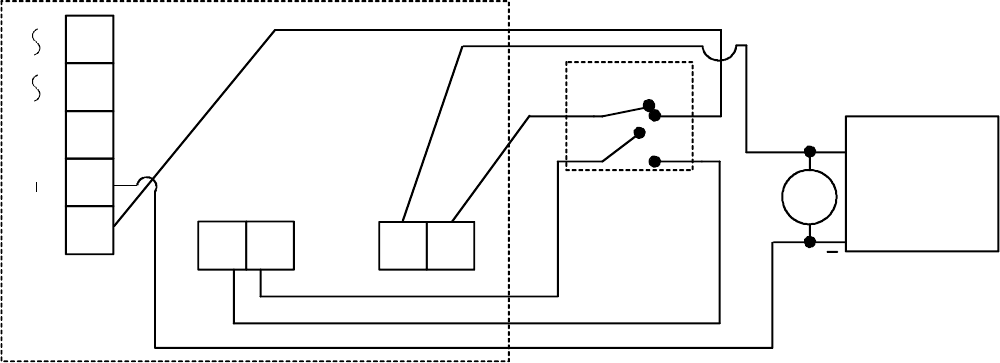
FIG. 7: DOUBLE BREAK WIRING FOR FREE EGRESS (TWO POLE SWITCH)
ELECTRIC
LOCK
MOV
CPU BOARD
NC
NC
NO
NO
WHEN THE EXIT SWITCH IS ACTIVATED, THE NC CONTACTS OPEN WHICH RELEASES THE FAIL
SAFE LOCK. AT THE SAME TIME, THE NO CONTACTS CLOSE WHICH ACTIVATES THE REX INPUT.
THIS DEENERGIZES THE LOCK CONTROL RELAY WHICH RELEASES THE LOCK "A SECOND TIME"
FOR THE AMOUNT OF TIME THAT HAS BEEN PROGRAMMED. IF THE DK-26 SUFFERS A FAILURE,
THE EXIT SWITCH CAN STILL RELEASE THE LOCK FOR SAFETY.
2 POLE
SWITCH
FAIL SAFE
SRC REX NC1
C1
AC IN F DC IN/OUT
+
+
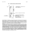
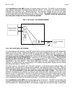
Note that Figure 6 shows a DC fail safe lock (virtually all fail safe locks are DC). Power could
either be furnished by an AC transformer which would connect to the “AC IN” terminals or a DC
power supply which would connect to the “DC IN/OUT” terminals.
If you have an SPDT exit switch available to double break REX, the connection is shown in
Figure 7. The difference is that you don’t use the SRC terminal at all. The REX terminal is
triggered from the +DC terminal via the NO contact of the SPDT switch.