


Rev. A.2, 10/03 Page-21
Put the unit into program mode and enter 8-0 to
assign this function to the HCD terminal or 8-1
to assign it to the UCD terminal. You will see
the two flash confirmation. Then, exit program
mode.
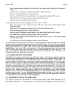
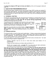
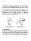
Finally connect a door switch as shown in the
drawing to the right and you will see that the door
will always relock immediately when it recloses
regardless of how much time is left on the timer.
The feature will operate when the door has been released from the keypad or from the REX
input (see Section 3.6). Note that to disable the anti-tailgating feature and return full function to
the HCD and UCD terminals, put the unit into program mode and enter 8-4. Note that the DK-
26 supports a more powerful anti-tailgating feature which incorporates an alarm signal through
the use of the programmable relay. Read Section 6.4 for details.
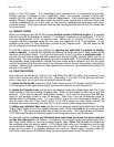
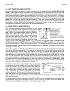
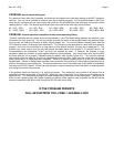
7.5 WIRING WITH SECURITRON'S TOUCH SENSE BAR AND MAGNALOCK
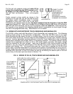
The DK-26 is often used with Securitron's Touch Sense Bar and magnetic lock. The following
drawing shows wiring for this particular configuration. Note that the REX input is not used.
Since touching the bar opens the door in a single motion, you do not want to activate the DK-
26's timer which would only serve to keep the lock released for a longer time, thereby reducing
security. Another potentially confusing element is that the Touch Sense Bar is also a powered
device which operates most reliably when it is constantly powered. The drawing shows a wiring
method that is applicable for either an AC or DC power supply (naturally, the supply voltage
must be matched to the lock voltage). Note that a variation of this wiring scheme could be
desired if you are using the second pole of the DK-26’s lock control relay to shunt an alarm
system (see Section 7.3). You would then want the Touch Bar to operate the DK-26’s lock
control relay in double break fashion so that the alarm system is shunted both for entry and exit.
Simply follow Figure 9 except also connect the blue and orange wires from the Touch Sensor to
terminals SRC and REX on the CPU board (as well as connecting the second pole of the lock
control relay to the alarm point as shown in Section 7.3).
FIG. 9: WIRING OF DK-26, TOUCH SENSE BAR AND MAGNALOCK
MAGNALOCK
TOUCH
SENSOR
BLACK
GREEN
BLACK
RED
WHITE
RED
CPU BOARD
NC1
C1
AC IN
F
DC IN/OUT
+
NOTE: SEE FIG. 2 FOR 12 WIRE
KEYPAD CABLE CONNECTIONS
IF AC POWER IS
BEING USED,
CONNECT 12
OR 24 VAC TO
AC IN TERMINALS
IF DC POWER IS
BEING USED,
CONNECT 12
OR 24 VDC TO
DC IN/OUT
TERMINALS. BE
SURE TO OBSERVE
POLARITY
POWER SUPPLY VOLTAGE MUST MATCH VOLTAGE OF MAGNALOCK
DC IN/OUT
+
SRC
UCD HCD
CONNECT A DOOR
SWITCH WHICH
OPENS WHEN THE
DOOR OPENS TO
UCD OR HCD
DEPENDING ON WHICH
COMMAND YOU CHOOSE
DOOR SWITCH