


9
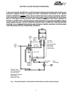
The location of the relief valve must be readily
accessible for servicing or replacement. To ac-
commodate the pressure relief valve, a suitable
fitting connected to an extension of a "T" fitting
can be sweated to the line. Make the T-fitting
extension long enough to ensure that the tem-
perature probe does not interfere with the wa-
ter flow. The relief pressure of the valve must
not exceed 150 psig. The relief temperature of
the valve must not exceed 210ºF and the dis-
charge capacity must be at least 165,000 Btu
per hour.
4. Connecting the pressure relief valve
A temperature and pressure relief valve must
be installed on the hot water line, close to the
heater. No valve is to be placed between the
relief valve and the heater. Installation shall
be made in such a manner that the discharge
from the temperature and pressure relief valve
will be conducted to a suitable place for dis-
posal when relief occurs. No reducing coupling
or other restriction may be installed in the dis-
charge line. The discharge line must be in-
stalled such that it allows complete drainage of
both the valve and the line.
NOTE: The regulator supplied with the
heater is an appliance level regulator de-
signed for low inlet pressure (less than 1/2
LB or 15"W.C.). DO NOT connect to an un-
regulated or high pressure propane line.
When your connections are made, check for
gas leaks at all joints (not just ones you made).
Apply some soapy water to all gas fittings and
gas valve. Soap bubbles are a sign of a leak.
NOTE: Do not apply soap solution to pilot fil-
ter screen or pilot orifice area. If you have a
leak, shut off the gas. After verifying that re-
quired gaskets are in place, tighten appropri-
ate fittings to stop leak. Turn the gas on and
check again with a soapy solution. Never test
for gas leaks using a match or flame.
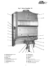
3. Connecting the water lines
Although water piping throughout your struc-
ture may be other than copper, copper piping
should be used for at least three feet before
and after the heater (follow local codes if more
stringent). Keep water inlet pipe to at least 3/4
inch diameter to allow the full flow capacity.
Remember that piping and water pressure must
allow sufficient flow to activate the heater when
drawing hot water from the top floor. If the hot
and cold connections are reversed, the heater
will not function. Be certain there are no loose
particles or dirt in the piping. Blow out or flush
water lines before connecting them to the
AquaStar 170 VP water heater.
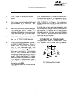
5. Vent pipe connection. WARNING: Do not
reduce the vent pipe size.
This appliance must be vented to the outside
following all local ordinances and specifications
for installing a gas appliance vent or chimney.
The venting system must be constructed so as
to develop a positive flow adequate to remove
flue gasses to the outdoors under all operating
conditions.
The appliance must be located as close as prac-
ticable to a chimney or vent. The vent pipe
sections must be fastened with sheet metal
screws. Keep in mind the minimum clearance
from the top of your heater. Remember also
that single wall vent pipe connectors require a
6 inch clearance from combustibles. National
Fuel Gas Code specifies double wall - Type "B"
- vent pipe be used in cold climates and for gas
vents running through attics. We consider
double wall vent pipe preferable in all circum-
stances. The vent connector should have as
much vertical rise as possible (minimum 12")
before any horizontal run. Any vent section
greater than 45 degrees from vertical is con-
sidered horizontal. Horizontal sections of vent
connectors must slope upwards at least 1/4 inch
for every foot of its horizontal length. Keep the
horizontal section short and avoid too many
elbows.
Note: Although the AquaStar has the same vent-
ing requirements as other Category I gas appli-
ances, certain features and specific use charac-
teristics make it more important to have a venting
system which exceeds minimum standards.
AquaStar thermostats modulate burner output.