


22
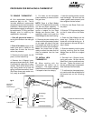
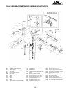
Before the water leaves the AquaStar, it passes two
energy CutOff Switches (ECO-#19). These are safety
devices which cause other gas controls to shut off all
the gas if the Heat Exchanger overheats.
GAS FLOW PATH
The appliance Gas Regulator (#23) at the inlet to the
heater ensures that gas pressure fluctuations don’t
over-pressure the heater. The Manual Gas Flow Shut-
off Valve (#14) provides a quick gas shut off right on
the heater.
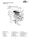
DESCRIPTION OF OPERATION OF
AQUASTAR 170
WATER PATH
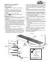
Cold water entering the Cold Water Inlet passes
through a nylon mesh Water Filter Screen (#21) which
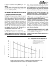
filters out dirt and debris. Water then passes through
the Water Flow Restrictor (#8) which prevents water
flow from exceeding 4.25 gallons per minute. The flow
control is there to help ensure that water does not flow
through the heat exchanger faster than the burners can
heat it. The restrictor can be removed if needed.
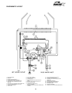
From the Flow Restrictor the water flows to #3, the
Water Valve. The only way out of the water valve is
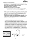
through a small hole, the venturi. Water squirting
through the venturi creates a pressure buildup on the
high pressure side of the diaphragm chamber. The
water pressure is lower on the other side of the venturi
hole. A small tube transfers this reduced pressure to
the low pressure side of the diaphragm chamber.
The pressure differential moves the diaphragm which
exerts force on the Push Rod (#24). At 1.1 gallons per
minute, the pressure differential becomes sufficient to
overcome the spring pressure of the Gas Flow Valve
(#7) opening the gas valve.
The water then moves through the Heat Exchanger (#1)
where it absorbs approximately 80% of the heat from
the burners. The balance of the heat is exhausted with
the flue gases. Located midway through the Heat
Exchanger, a Water Temperature Probe (#17) senses
water temperature. It works with the Gas Flow Valve
(#6) to regulate the amount of gas to the burners.
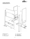
The E.C.O.s are integrated with the pilot light. An
Electro-Magnet in the Gas Valve ensures that gas
flows to the burner only when there is a pilot light to
ignite it. The Pilot Knob (#15) shuts gas off to the
burners while you light the pilot. You must hold the
Pilot Knob in at the single flame position long enough
for it to heat the Thermocouple (#12).
The water activated gas valve (#7) opens and shuts in
response to water flow. On heaters fueled with LP Gas,
a Slow Ignition Device (#4) gradually increases gas
flow for ignition. The Natural Gas models have no such
device because Natural Gas is delivered at a much
lower pressure.
The Thermocouple (#12) produces a very small amount
of electricity (0.03 volts) when it is exposed to a flame.
This electricity is just enough to hold open the spring-
loaded Electromagnet Gas Flow Shut-off Valve (#13).
If the thermocouple is not hot enough, the spring closes
the valve. Pushing #15 in the single flame position,
allows gas to flow to the pilot. Gas can’t go to the
burners until the pilot has been lighted and the knob has
been turned to the three flame position and released.
If a malfunction causes the Heat Exchanger to get too
hot, the E.C.O.s (#19) interrupt the electrical circuit
between the thermocouple and electromagnet. This
safety feature shuts off the gas to both burners and the
pilot. Manual relighting is required once the problem is
corrected.
The Thermostatic Gas Flow Modulator (#5) works with
the Water Temperature Probe (#17) to modulate the
amount of gas delivered by the thermostatically
controlled Gas Flow Valve, (#6). Initially the water in
the Heat Exchanger is cold, the Gas Flow Valve allows
a full flow of gas to the Burners (#2). Then depending
on the flow rate, inlet water temperature and/or the
Thermostatic Temperature Selector (#20), the Gas
Flow Valve (#6) adjusts gas flow anywhere from 0 to
165,000 Btu's.