


4
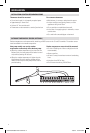
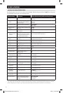
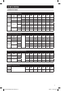
WIRING TERMINAL
Wire specifications:
18-24 gauge thermostat wire
Installation notes:
• Ensure power at the HVAC equipment is off.
• Loosen screw terminals, insert stripped wire and
re-tighten.
• Push the excess wire back into the opening and plug
the wall opening to prevent drafts.
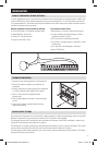
INSTALLATION
C – Common (optional when powered by batteries)
B – Reversing valve
1
O – Reversing valve
1
Y – 1st stage cooling / compressor
Y2 – 2nd stage cooling / compressor
G – Fan
RC – 24VAC supply cooling
2
R – 24VAC supply heating
2
W2 – 2nd stage heat / auxiliary
W – 1st stage heat / auxiliary
L – System fault indicator (optional) (heat pump only)
S1 & S2 – outdoor temperature sensor (optional)
T1 & T2 – remote temperature sensor (optional)
1
O and B terminals are both de-energized when system mode is
OFF or in AUTO when the heating and cooling equipment is idle.
2
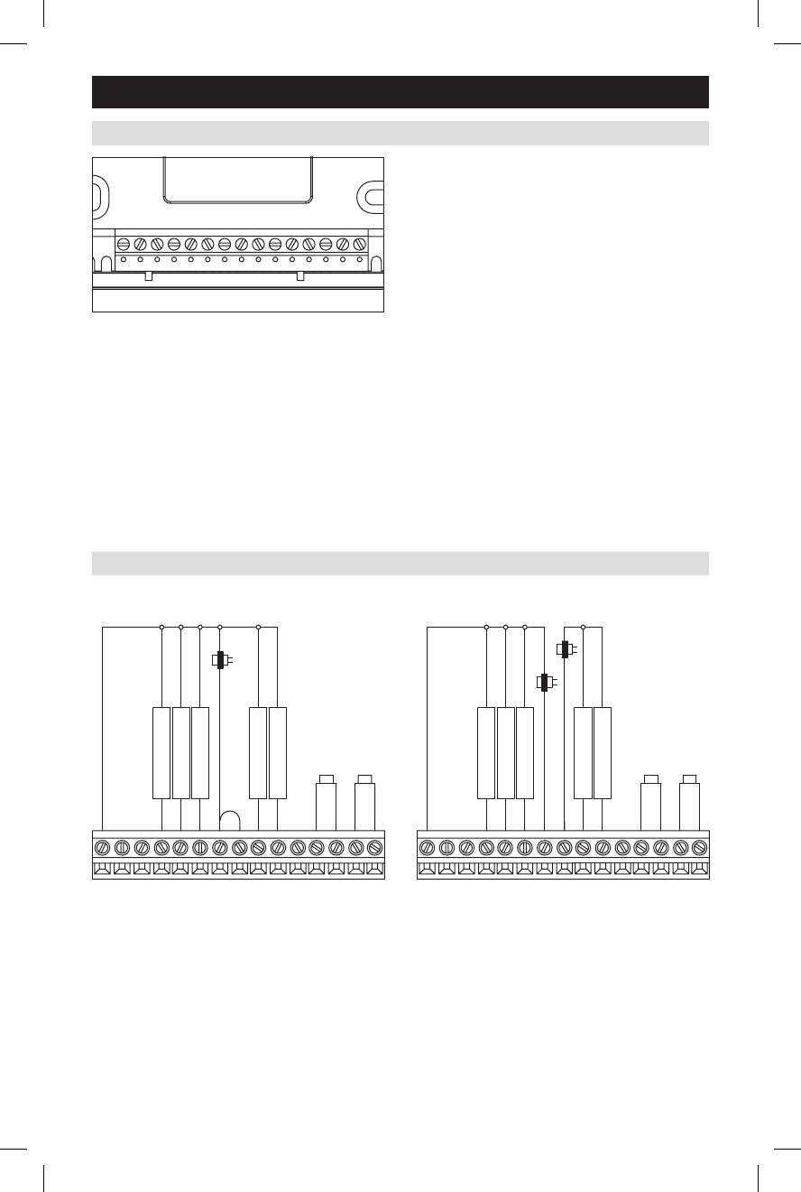
Jumper between RC & R is used in single transformer systems
(see wiring diagrams).
C
BY
ORC
RG
Y2 W2
LT2
T1
S1
S2
W
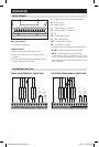
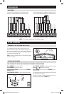
SINGLE TRANSFORMER (USE JUMPER WIRE) TWO TRANSFORMERS (REMOVE JUMPER WIRE)
JUMPER
OUTDOOR TEMP
SENSOR
1st HEATING
1st COOLING
FAN
2nd HEATING
2nd COOLING
NOT USED
NOT USED
TRANSFORMER
REMOTE TEMP
SENSOR
NOT USED
GY2YOBWRC RW2S2LCS1T1T2
NOT USED
NOT USED
2nd COOLING
2nd HEATING
FAN
1st COOLING
1st HEATING
OUTDOOR TEMP
SENSOR
COOLING
HEATING
REMOTE TEMP
SENSOR
NOT USED
TRANSFORMER
TRANSFORMER
GY2YOBWRC RW2S2LCS1T1T2
CONVENTIONAL HEAT/COOL
61000729A 8600 Tstat Install.indd 4 10/8/10 10:32:35 AM