


3
WHOLE-HOUSE DEHUMIDIFIER OPERATION AND INSTALLATIONS
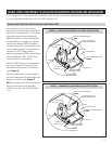
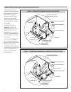
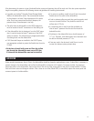
In this configuration, the dehumidifier will pull air from the principle living space or the return duct. The air passes through the
dehumidifier, where moisture is removed, and then is returned to the HVAC system downstream of the cooling coil in the main supply
duct. The dehumidifier will turn on with the first HVAC blower call in each time interval (see CONTROL AND SETUP section on page
12 to set time interval) in order to get an accurate air sample. If no HVAC blower call occurs during the time interval, the dehumidifier
will activate its own internal blower and take an air sample. If the incoming air is above the set point, the dehumidifier compressor
will turn on. Even if the HVAC blower shuts off, the dehumidifier will continue to run until the set point is satisfied. If an HVAC call
starts when the dehumidifier is running the dehumidifier will continue to run.
INSTALLATION OVERVIEW
SEE PAGE
STEP 1: Select the type of installation.
a. Whole-house . . . . . . . . . . . . . . . . . . . . . . . . . . .3
b. Localized . . . . . . . . . . . . . . . . . . . . . . . . . . . . . .4
c. Whole-house Convertible to Localized . . . . . . . .5
STEP 2: Determine if outside ventilation will be included
with dehumidification system
(Ventilation time calculation included) . . . . . . . . .11
SEE PAGE
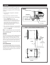
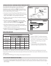
STEP 3: Select location and mounting method
for dehumidifier . . . . . . . . . . . . . . . . . . . . . . . . . . .7
STEP 4: Install ductwork including dampers if used . . . . . .8
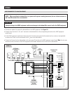
STEP 5: Install wiring . . . . . . . . . . . . . . . . . . . . . . . . . . . .10
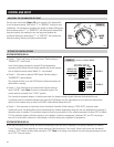
STEP 6: Set up control . . . . . . . . . . . . . . . . . . . . . . . . . . .12
STEP 7: Checkout system . . . . . . . . . . . . . . . . . . . . . . . . .13
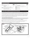
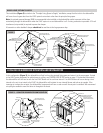
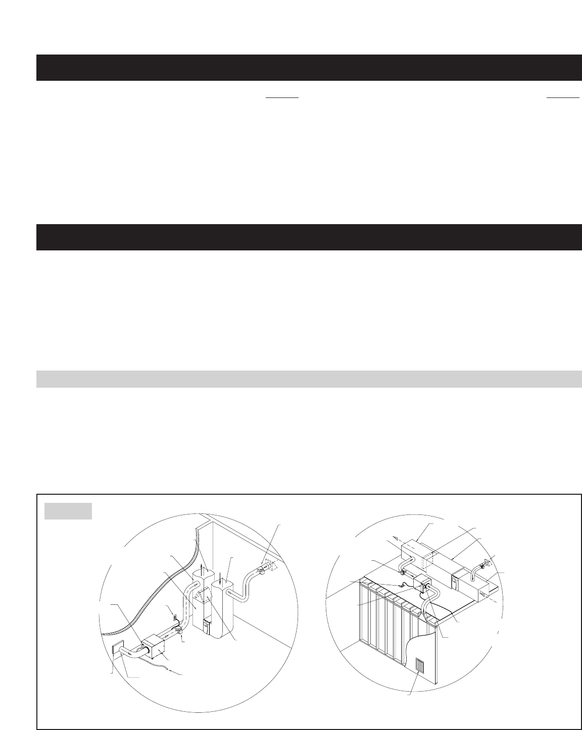
In this installation, the inlet to the dehumidifier will come from a new return duct installed in a principle living space. Air is drawn
from this area, through the dehumidifier and into the supply duct of the HVAC system, as shown in Figure 1.
Note: Due to backflow of air through the dehumidifier while it is not running, it is recommended to install an optional powered
damper (6508). A wiring connection is provided. A 24-volt transformer (not provided) is required to power the damper.
A barometric or other backdraft damper should not be used due to the large pressure drop.
WHOLE-HOUSE, PRINCIPLE LIVING SPACE TO SUPPLY
RETURN DUCT
VENTILATION (OUTSIDE AIR)
CONTROL DAMPER (OPTIONAL)
SUPPLY DUCT
DEHUMIDIFIER CONTROL
WITH SET POINT KNOB
INLET GRILL
PRINCIPLE
LIVING SPACE
115 VAC
CONDENSATE HOSE
(TO COMMON DRAIN)
HVAC/FURNACE SYSTEM SHOWN
IN HORIZONTAL ORIENTATION
COOLING COIL
AIR FILTER
ACCESS
PANEL
DEHUMIDIFIER CONTROL
WITH SET POINT KNOB
EQUIPMENT ROOM:
• BASEMENT (SHOWN)
• ATTIC (SHOWN)
• GARAGE
• CLOSET
• CRAWL SPACE
AIR IS PULLED
FROM PRINICIPLE
LIVING SPACE
PRINCIPLE
LIVING SPACE
DEHUMIDIFIED AIR IS SUPPLIED
DOWN STREAM FROM COOLING COIL
TO MINIMIZE EVAPORATION OFF COOLING COIL
SUPPLY DUCT
RETURN
DUCT
HVAC / FURNACE
INLET GRILL
DEHUMIDIFIER
COOLING COIL
(A-COIL SHOWN)
115VAC
VENTILATION (OUTSIDE AIR)
CONTROL DAMPER (OPTIONAL)
DAMPER
(OPTIONAL)
CONDENSATE HOSE
(TO COMMON DRAIN)
DAMPER
(OPTIONAL)
DEHUMIDIFIED AIR IS SUPPLIED
DOWN STREAM FROM COOLING COIL
TO MINIMIZE EVAPORATION OFF COOLING COIL
90-775
FIGURE 1