11
OPTIONAL VENTILATION – DAMPER AND OUTDOOR TEMPERATURE SENSOR
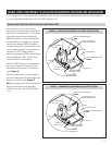
• The Aprilaire
®
Normally-Closed Damper (Model 6506) needs to be
installed in the outside air intake. It should be wired to the terminals
labeled “VENT DAMPER” on the dehumidifier control board.
• In addition to these instructions, follow all installation instructions
supplied with the damper.
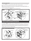
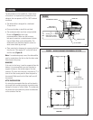
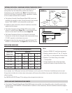
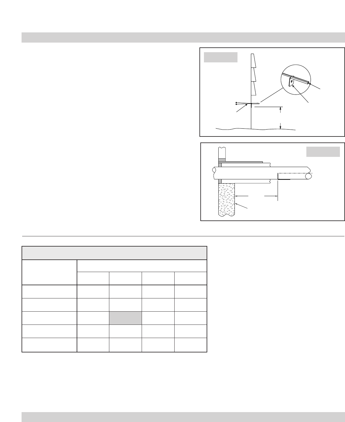
• The Outdoor Temperature Sensor (Model 4278) can be installed
outside in a shaded location (Figure 11) or in an outside air intake
duct, but no more than 3 feet from the outside (Figure 12).
• The Outdoor Temperature Sensor is not affected by wire length.
However, do not route the wire alongside wires carrying high voltage
(115 VAC or greater), as interference may occur.
• Connect the wires from the sensor into the terminals labeled “ODT
SENSOR” on the dehumidifier. See Figure 10 for terminal locations.
This installed option allows outside air to be combined with the air
cycling feature from the dehumidifier, provided the outside air
temperature is in the acceptable range. Note: The dehumidifier can
control the HVAC blower to provide air cycling, regardless of whether
or not an outdoor ventilation duct is installed.
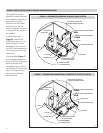
INSTALL AND WIRE POWERED BACKFLOW DAMPER
• If the Aprilaire
®
Normally-Closed Damper (Model 6508) needs to be installed in the dehumidifier outlet, it should be wired to the
terminals labeled “DEH DAMPER” of the dehumidifier. In addition to these instructions, follow all installation instructions supplied
with the damper.
NORTH, EAST
OR WEST SIDE
OF HOME
OUTDOOR
TEMPERATURE
SENSOR
SENSOR
SENSOR
BRACKET
ABOVE EXPECTED
SNOW LINE
OUTDOOR
TEMPERATURE SENSOR
LEADS
36" MAX.
CENTER LINE
OUTSIDE WALL
B2202617-D
B2202617-E
FIGURE 11
FIGURE 12
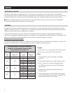
House Size
Bedrooms
(square feet)
2345
1000-1500 15 20 25 25
1501-2000 20 25 25 30
2001-2500 20 25 30 30
2501-3000 25 30 30 35
3001-3500 25 30 35 40
Notes:
1. Based on ASHRAE 62.2 ventilation requirement.
2. Based on outside air duct of 6” dia., 20’ long flex
duct, 0.08 in. w.c. static pressure at fresh air duct.
3. Based on ‘Cycle Period’ being in the default
(1 hour) position.
4. A longer outside air duct and/or lower static
pressure will require a longer Ventilation Time.
VENTILATION GUIDELINES
Air Cycling Time Setting (min./hr.)
As an example, for a 2,500 square foot home with 3 bedrooms, set the cycle time to 25 minutes of ventilation per one-hour cycle.
A longer fresh air intake duct or lower return static pressure will increase the ventilation time required. Additionally, local codes may
affect the setting.
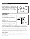
See CONTROL AND SETUP (page 12) for setting up the cycle period and cycle time.


