5
OPERATION NOTES FOR MODULATING CONTROL
FOR MODEL 1160 & 1180
CAUTION
A high relative humidity setting on the Control may cause
excessive condensation on windows and within walls. Set the
relative humidity in accordance with the instructions in this manual.
Do not set the relative humidity higher than recommended.
As explained in the ‘Principles of Operation’ section of this manual, when
configured for modulating control, the Automatic Steam Humidifier Control
sends a 0-10V signal to the humidifier to vary the capacity of the Steam
Humidifier depending on where the measured return air relative humidity
falls relative to the set-point as well as the proportional control band. This
will result in a more precise control of relative humidity.
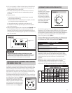
The proportional control band can be set to 6%, 9%, 12%, or 15% RH. The
factory-setting is 12%. Note that the proportional control band is centered
on the RH set-point. Refer back to Figure 1.
If the humidifier is cycling on and off too
frequently, the proportional control band
setting may need to be widened. To change,
use a small flat-head screwdriver to rotate
the potentiometer in the Automatic Steam
Humidifier Control board. See Figure 11.
6
912
15
FIGURE 11
90-901
AUTOMATIC MODE OPERATION NOTES
The Automatic Steam
Humidifier Control is installed
in the return duct. During the
first heating season, the
Automatic Steam Humidifier
Control needs to be adjusted
to match the requirements and
construction of the conditioned
space. Please follow these
steps when adjusting the
Control (refer to Figure 12)
T
E
S
T
/
R
E
S
E
T
2
3
5
4
6
1
7
AUTOMATIC MODE
O
F
F
FIGURE 12
90-902
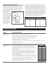
Turn the dial to a setting of “4”. At this setting, when the Outdoor
Temperature is 20°F, the indoor relative humidity set-point of the Automatic
Steam Humidifier Control will be 35% RH. During the next 24-48 hours, it
may be necessary to adjust the dial for more or less humidity, depending on
the occupants’ comfort and the requirements of the conditioned space.
Refer to the ‘Operation Guide’ (Table 1).
During the coldest portion of the first heating season, minor adjustments may
be necessary. This is dependent upon the unique features and construction of
the conditioned space. Refer to the ‘Operation Guide’ (Table 1).
TABLE 1: Operation Guide
Condition Solution
Condensation on windows. Reduce the setting on the control
dial by 1 increment.
Lack of humidity. Increase the setting on the control
dial by 1 increment.
The relative humidity in the conditioned space will now be accurately
controlled and should need no further adjustment during future heating
seasons. Make note of the dial setting in the event the knob is temporarily
moved when performing annual maintenance of the Aprilaire Steam
Humidifier.
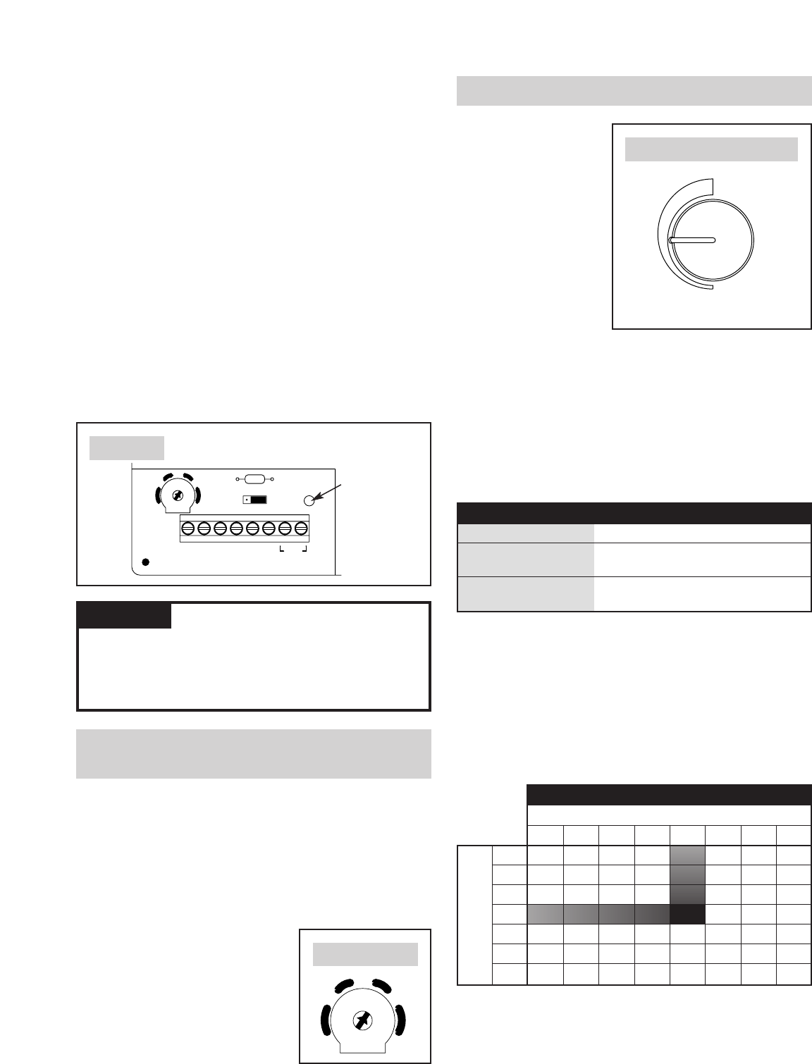
Table 2 below shows the way the Automatic Steam Humidifier Control
automatically adjusts the relative humidity based on the outdoor
temperature. For example, when the knob is set to “4” and the outdoor
temperature is 20°F, the conditioned space will be controlled to 35% RH.
TABLE 2: Relative Humidity Guide
Outdoor Temperature (°F)
-20 -10 0 10 20 30 40 50
1 –––10
15 20 25 30
2 – – 12 17 22 27 32 37
3 –13182328 33 38 43
4 15 20 25 30 35 40 45 50
5 22 27 32 37 42 47 52 55
6 28 33 38 43 48 53 55 55
7 35 40 45 50 55 55 55 55
Dial Setting
6. If all is set up properly, the ‘Steam’ indicator light on the humidifier will
illuminate and the heaters will be energized. In the ‘Test’ position, the
humidity demand will last for one minute.
7. If the ‘Steam’ indicator light does not illuminate when the Control is
turned to the ‘Test’ position, refer to the troubleshooting section of
this manual.
8. Setting the Control:
• If using Automatic Mode and the conditioned space is occupied,
set the Control to knob-setting 4.
• For Manual Mode and the conditioned space is occupied, set to 35%
or to a level that matches the application’s needs.
• If the conditioned space is unoccupied, set the Control to ‘Off’
For information on the initial adjustment period, refer to the operation
notes in the next section.
9. Make sure the Red Diagnostic Light on the Control (see Figure 10) is not
lit. If the Red Diagnostic Light is lit, re-check the wiring. If the Red
Diagnostic Light does not go off, refer to the troubleshooting section of
this manual. Note that the Red Diagnostic Light will turn on momentarily
when first powered up.
R17
H+24V CI-I+ ODTH-
15
129
6
JP2
123
FIGURE 10
Red Diagnostic
Light
90-891


