4
STEP 6: ROUTE THE WIRE TO CHOSEN
SENSOR LOCATION
Run wire to the outdoor temperature sensor. Sensor is not affected by lead
length up to 300 feet. Use standard thermostat wire. Do not run outdoor
temperature sensor alongside wires carrying high voltage (120 VAC
or higher).
STEP 8: WIRE THE CONTROL TO THE HUMIDIFIER
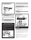
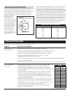
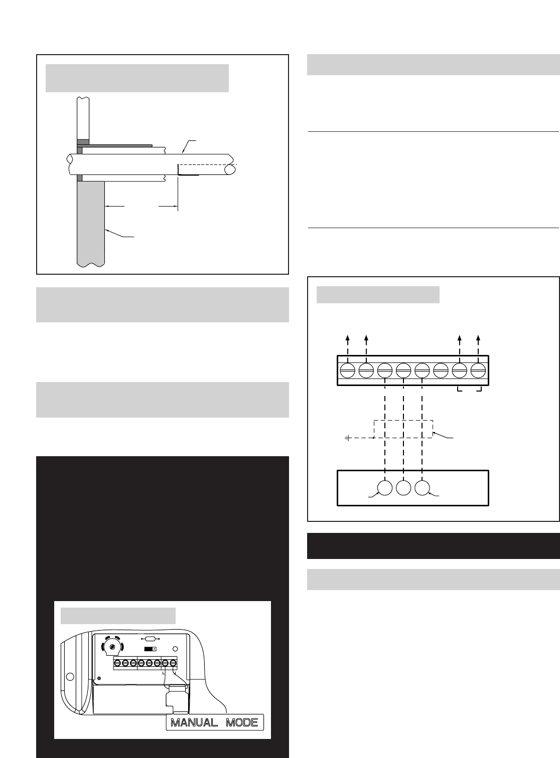
Wire the Control to the field wiring terminal block of the Steam Humidifier
according to Figure 9. Use 3-wire shielded cable with ground for the wiring
from the Control to the Humidifier. Note the terminal designations below.
AUTOMATIC STEAM HUMIDIFIER CONTROL:
I+, I- Serial Communications (for optional devices)
24V +24 VDC input power
C Common
H+ Command Signal to Steam Humidifier
H- Command Signal to ground (not used)
ODT Outdoor Temperature Sensor
STEAM HUMIDIFIER:
30 +24 VDC output power
C Humidifier Common
1 Command Signal from Control
STEP 7: ATTACH SENSOR WIRE TO AUTOMATIC
STEAM HUMIDIFIER CONTROL
Strip wires 1/4 inch, and insert the wires from the Sensor into the terminals
labeled “ODT” on the Automatic Steam Humidifier Control.
INSTALLING THE AUTOMATIC STEAM
HUMIDIFIER CONTROL FOR MANUAL OPERATION
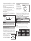
1. Insert the Manual Mode Resistor Case into the terminals
labeled “ODT” on the Automatic Steam Humidifier Control.
2. Snap the Manual Mode Resistor Case into the slot
provided so that Resistor Case sticks out from the bottom
edge of the base.
3. Remove the control knob and apply the Manual Mode
label to the cover, aligning the sticker and knob holes.
Re-install the knob.
6
912
15
H- ODTI+ I- C24V H+
321
JP2
R17
FIGURE 8 – Manual Mode
90-899
I+ I- H-
30
C1
24V C H+
ODT
3-WIRE SHIELDED
CABLE W/GROUND
HUMIDIFIER PANEL
SHIELD GND LUG
COMMAND
SIGNAL
+24VDC
COMMON
TO OUTDOOR
TEMPERATURE
SENSOR
SERIAL COMMUNICATION
TO APRILAIRE MODEL 8570
THERMOSTAT (OPTIONAL)
AUTOMATIC
STEAM
HUMIDIFIER
CONTROL
STEAM
HUMIDIFIER
FIELD WIRING
TERMINAL
BLOCK
FIGURE 9 – Wiring Diagram
90-900
SYSTEM CHECKOUT
OPERATION
1. For system test, be sure that all Steam Humidifier plumbing, distribution,
and electrical connections are set-up in accordance with the instructions
in the Steam Humidifier Installation, Operation, and Maintenance Manual
and all precautions therein are followed.
2. Turn on the water supply to the humidifier. Make sure the drain valve
is closed.
3. Turn on power to the humidifier.
4. Set up a fan call at the thermostat. If the humidifier is configured to bring
on the equipment fan when a demand for humidity is recognized, skip to
the next step.
5. Initiate a humidity demand from the Control by rotating the control
knob of the Automatic Steam Humidifier Control clockwise to the
‘Test’ position.
36" MAX.
CENTER
LINE
OUTSIDE WALL
FRESH AIR INTAKE
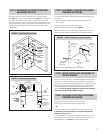
FIGURE 7 – Alternate Location for Outdoor
Temperature Sensor
90-896


