2
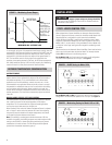
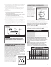
MEASURED %RH - SETPOINT %RH
OUTPUT
Note:
The Proportional
Control Band
can be adjusted
to 6%, 9%, 12%,
or 15% RH. The
factory setting
of 12% is
depicted at left.
PROPORTIONAL
CONTROL BAND
0 +6-6
10 VDC
5 VDC
0 VDC
FIGURE 1 – Modulating Control Output
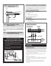
90-890
R17
H+24V CI-I+ ODTH-
15
129
6
JP2
123
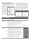
FIGURE 2 – On/Off Setting for Model 1150
90-891
6
912
15
H- ODTI+ I- C24V H+
R17
321
JP2
FIGURE 3 – Modulating Setting for Model 1160 or 1180
90-892
AUTOMATIC MODE
The automatic mode is the preferred method when the application
requires that the Control automatically adjust the RH set-point based on
the outdoor temperature. This is recommended for all comfort-based
applications such as office buildings, schools, day cares, etc. It is also
recommended for any application where the primary concern is to avoid
the potential for condensation that can form on areas within the building
such as windows and within walls. When installed in this mode, the
Control utilizes an Outdoor Temperature Sensor that will track the actual
outdoor temperature. The Control then automatically adjusts the desired
indoor RH.
MANUAL MODE (SPECIFIC SET-POINT CONTROL)
The manual mode is the preferred method when the application requires
that a specific set-point be maintained regardless of the outdoor
temperature. This is recommended for all process-based applications
such as print shops, book stores, test facilities, etc.
When installed in this mode, the Outdoor Temperature Sensor is replaced
with a “manual” resistor case that prevents the Control from adjusting
the space RH set-point based on the outdoor temperature, and controls
to the specific set-point selected on the Control.
Note: If the building is not designed to handle the amount of RH the
humidifier is supplying, the building occupants may need to adjust the RH
setting on the Control to a lower value during extreme days to prevent
condensation on interior surfaces. The RH setting should be adjusted
upward when the outdoor temperature goes up.
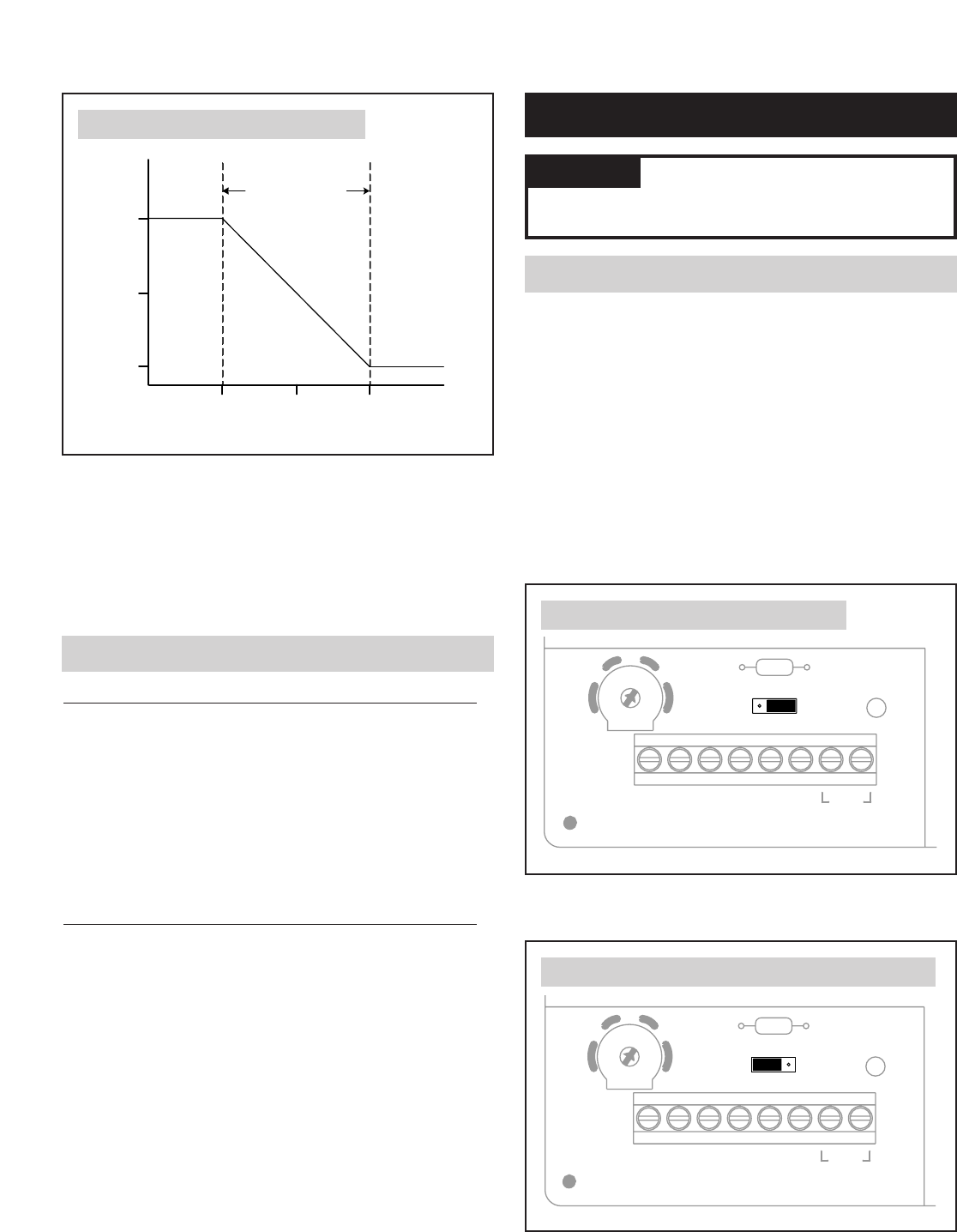
As an example, using the 12% proportional band (factory-setting), when the
measured RH is 6% above the set-point the output will be 0 VDC; when the
measured RH is 6% below set-point the output will be 10 VDC; when the
measured RH is 3% below set-point the output will be approximately 7.5
VDC. The humidifier uses this varying signal to time-proportion the
operation of the heating elements in the tank. 10 VDC output corresponds
with 100% humidifier capacity, 5 VDC with 50% capacity, etc. Modulating
control will result in a more precise control of relative humidity.
OUTDOOR TEMPERATURE COMPENSATION
STEP 1: VERIFY CONTROL TYPE
INSTALLATION
When shipped with a Steam Humidifier, the Automatic Steam Humidifier
Control is preset at the factory to match the humidifier model: Model 1150
Steam Humidifier is configured for on/off control while the Model
1160/1180 Steam Humidifier is configured for modulating control. When
shipped as a replacement (Model 57), the Control is preset for use with a
Model 1150 (i.e., on/off control). If using the Model 57 with a Model 1160
or 1180, the ‘control type’ setting must be changed for modulating control.
See below.
Remove the door to the Automatic Steam Humidifier Control and look at the
area on the circuit board above the terminal block. The three-pin header
labeled JP2 should be set in the following manner:
For the Model 1150, the Control must be set to the on/off configuration.
The shunt must be placed on the 2 & 3 pins. See Figure 2.
For the Model 1160 or 1180, the Control must be set to the modulating
configuration. The shunt must be placed on the 1 & 2 pins. See Figure 3.
CAUTION
Improper jumper settings may damage humidifier.
The shunt on the JP2 header pin must be set in accordance with the
instructions in this manual.


