


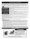
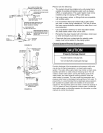

Explosion Hazard
• Usea newCSAapprovedgassupplyline.
• Installa shut-offvalve.
• Donot connecta naturalgaswaterheatertoanL.P.gas
supply.
• Donot connectanL.P.gaswaterheatertoa naturalgas
supply.
• Failureto follow theseinstructionscanresultindeath,
explosion,or carbonmonoxidepoisoning.
Gas Requirements
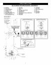
IMPORTANT: Read the rating plate to be sure the water
heater is made for the type of gas you will be using in
your home. This information will be found on the rating
plate located near the gas control valve/thermostat. If the
information does not agree with the type of gas available,
do not install or light. Call your dealer.
NOTE: An odorant is added by the gas supplier to the gas
used by this water heater. This odorant may fade over an
extended period of time. Do not depend upon this odorant
as an indication of leaking gas.
Gas Piping
The gas piping must be installed according to all local and
state codes or, in the absence of local and state codes, the
"National Fuel Gas Code", ANSI Z223.1(NFPA 54)-current
edition.
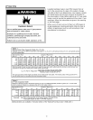
Tables 1 and 2 on the following page provide a sizing
reference for commonly used gas pipe materials. Consult
the "National Fuel Gas Code" for the recommended gas
pipe size of other materials.
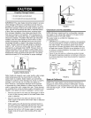
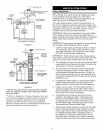
NOTE: Use pipe joint compound or teflon tape marked as
being resistant to the action of petroleum [Propane (L.R)]
gases (See Figure 3.)
1. Install a readily accessible manual shut-off valve in the
gas supply line as recommended by the local utility.
Know the location of this valve and how to turn off the
gas to this unit.
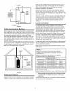
2. Install a drip leg (if not already incorporated as part of
the water heater) as shown. The drip leg must be no
less than three inches long for the accumulation of dirt,
foreign material, and water droplets.
3. Install a ground joint union between the gas control
valve/thermostat and the manual shut-off valve. This
is to allow easy removal of the gas control valve/
thermostat.
4. Turn the gas supply on and check for leaks. Test all
connections by brushing on an approved noncorrosive
leak-detection solution. Bubbles will show a leak.
Correct any leak found.
MANUAL GAS _
SHUT-OFF VALVE--_
GROUND-------=
JOINT
UNION
CHECK WITH
LOCAL UTILITY
FOR MINIMUM HEIGHT
3" MINIMUM
t/
DRIP LEG_
Gas Pressure
DISCHARGE PiPE
(DO NOT PLUG OR CAP)
_6" MAXIMUM
_ T AIR GAP
SUITABLE DRAIN "--_'_ f
FIGURE 3.
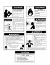
Explosion Hazard
• Gas leaks can not always bedetected by smell.
• Gas suppliers recommend that you usea gas
detector approved by UL or CSA.
• For more information, contact your gassupplier.
• If a gas leak is detected, follow the "What to do ifyou
smell gas" instructions on the cover of this manual.
IMPORTANT: The gas supply pressure must not exceed the
maximum supply pressure as stated on the water heater's rating
plate. The minimum supply pressure is for the purpose of input
adjustment.
Gas Pressure Testing
IMPORTANT: This water heater and its gas connection must
be leak tested before placing the appliance in operation.
• If the code requires the gas lines to be tested at a
pressure exceeding 14"W.C., the water heater and its
manual shut-off valve must be disconnected from the gas
supply piping system and the line capped.
• If the gas lines are to be tested at a pressure less than
14" W.C., the water heater must be isolated from the gas
supply piping system by closing its manual shut-off valve.
NOTE: Air may be present in the gas lines and could prevent
the pilot from lighting on initial start-up. The gas lines should
be purged of air by a qualified technician after installation of
the gas piping system. While purging the gas piping system
of air, insure that the fuel is not spilled in the area of the
water heater installation, or any source of ignition. If the
fuel is spilled while purging the piping system of air follow
the "WHAT TO DO IF YOU SMELL GAS" instructions on
the cover of this manual.