


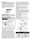
• Be sure to follow the manual(s) shipped with the air
handler system.
• This water heater is not to be used as a replacement
for an existing boiler installation.
• Do not use with piping that has been treated with
chromates, boiler seal or other chemicals and do not
add any chemicals to the water heater piping.
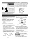
• If the space heating system requires water
temperatures in excess of 120°F, a tempering valve
or an anti-scald device should be installed per its
manufacturer's instructions in the domestic (potable)
hot water supply to limit the risk of scald injury.
• Pumps, valves, piping and fittings must be compatible
with potable water.
• A properly installed flow control valve is required to
prevent thermosiphoning. Thermosiphoning is the
result of a continuous flow of water through the air
handler circuit during the off cycle. Weeping (blow off)
of the temperature and pressure relief valve (T & P)
or higher than normal water temperatures are the first
signs of thermosiphoning.
• The domestic hot water line from the water heater
should be vertical past any tempering valve or supply
line to the air handler to remove air bubbles from the
system. Otherwise, these bubbles will be trapped in the
air handler heat exchanger coil, reducing the efficiency.
• Do not connect the water heater to any system or
components previously used with non-potable water
heating appliances when used to supply potable water.
Some jurisdictions may require a backflow preventer in the
incoming cold water line. This may cause the temperature
and pressure relief valve on the water heater to discharge
or weep due to expansion of the heated water. A
diaphragm-type expansion tank suitable for potable water
will normally eliminate this weeping condition. Please
read and follow the manufacturer's instructions for the
installation of such tanks.
Also see Water System Piping for additional instructions
on the safe and correct installation and operation of this
water heater.
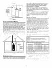
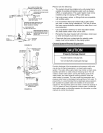
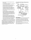
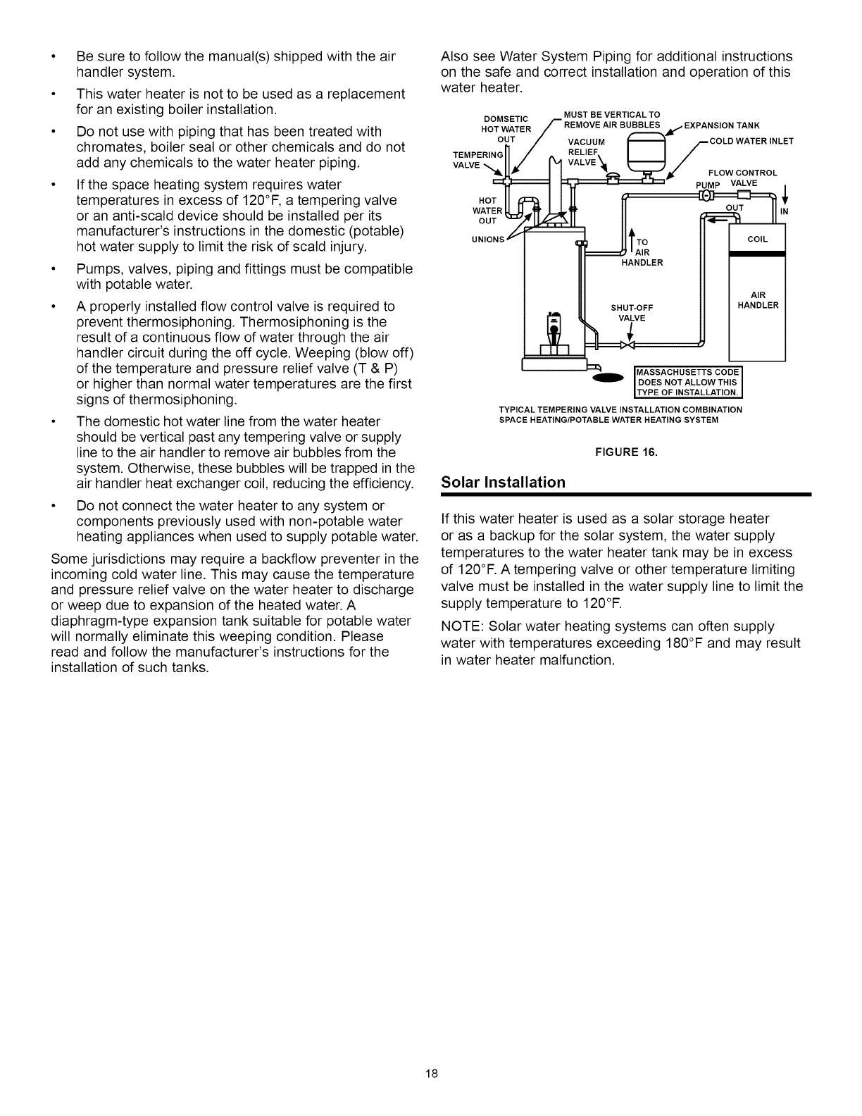
MUST BE VERTICAL TO
HDoOTMwSET/CRf REMOVE AIR BUBBLES _, EXPANSION TANK
OUT / VACUUM _ pCOLD WATER INLET
TEMPERINGnA RELIEF.I I /
VALVE- H , 1%4 VALVE _., _ /
"_ _1_ • _/" FLOW CONTROL
_JJ_ J 1:__ PUMP VALVE
HOTHI 11[I
WATERLI II == OUT ,N
uO s2 II CO,L'
=UtT,o
HANDLER //
I AIR /
SHUT E FE
MASSACHUSETTS CODE
DOES NOT ALLOW THIS
TYPE OF NSTALLAT ON.
TYPICAL TEMPERING VALVE INSTALLATION COMBINATION
SPACE HEATING/POTABLE WATER HEATING SYSTEM
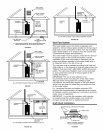
Solar Installation
FIGURE 16.
If this water heater is used as a solar storage heater
or as a backup for the solar system, the water supply
temperatures to the water heater tank may be in excess
of 120°F. A tempering valve or other temperature limiting
valve must be installed in the water supply line to limit the
supply temperature to 120°F.
NOTE: Solar water heating systems can often supply
water with temperatures exceeding 180°F and may result
in water heater malfunction.
18