


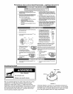
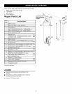

When ordering repair parts always give the following information:
1. Model, serial, and product number
2. Type of gas
3. Item number
4. Parts description
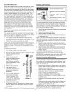
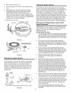
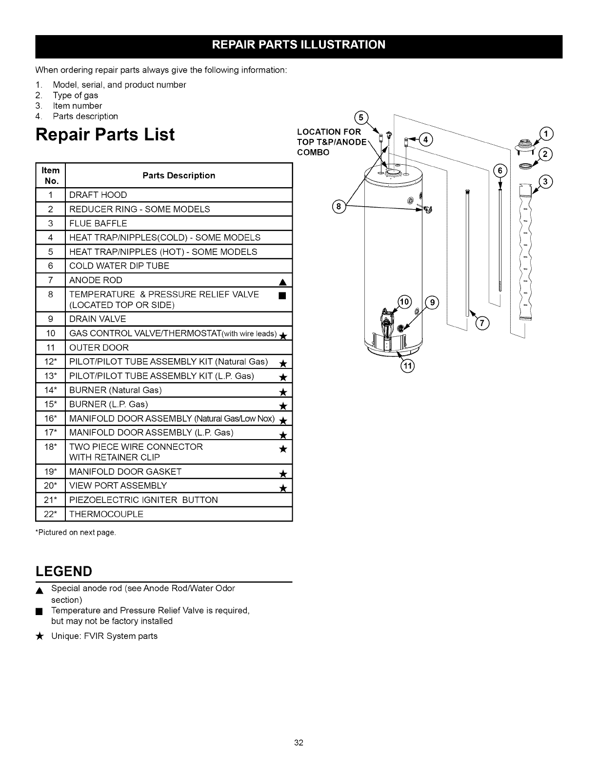
Repair Parts List
Item
Parts Description
No.
1 DRAFT HOOD
2 REDUCER RING - SOME MODELS
3 FLUE BAFFLE
4 HEAT TRAP/NIPPLES(COLD) - SOME MODELS
5 HEAT TRAP/NIPPLES (HOT) - SOME MODELS
6 COLD WATER DIP TUBE
7 ANODE ROD •
8 TEMPERATURE & PRESSURE RELIEF VALVE •
(LOCATED TOP OR SIDE)
9 DRAIN VALVE
10 GAS CONTROL VALVE/TH ERMOSTAT(with wire leads)
11 OUTER DOOR
12" PILOT/PILOT TUBE ASSEMBLY KIT (Natural Gas)
13" PILOT/PILOT TUBE ASSEMBLY KIT (L.R Gas)
14" BURNER (Natural Gas) y_.
15" BURNER (L.R Gas) "k
16" MANIFOLD DOOR ASSEMBLY (NaturalGas/Low Nox) ._
17" MANIFOLD DOORASSEMBLY (L.R Gas) ._
18" TWO PIECE WIRE CONNECTOR ._
WITH RETAINER CLIP
19" MANIFOLD DOOR GASKET ._
20* VIEW PORT ASSEMBLY
21" PIEZOELECTRIC IGNITER BUTTON
22* THERMOCOUPLE
*Pictured on next page.
LOCATION FOR(_
TOP
COMBO
,o
LEGEND
• Special anode rod (see Anode Rod/Water Odor
section)
• Temperature and Pressure Relief Valve is required,
but may not be factory installed
Y_- Unique: FVIR System parts
32