


9
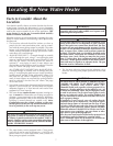
Locating the New Water Heater (cont’d)
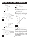
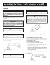
Figure 2
9″ min. from
any overhang
12″ min.
C
Lof Flue
Must maintain
adequate service
and maintenance
accessibility.
Range of degrees
available for vent
pipe installation.
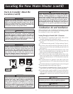
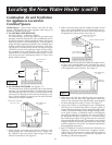
Figure 4
24″
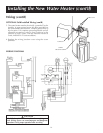
NATURAL DRAFT (GRAVITY),
DIRECT VENT, POWER VENT
OR POWER DIRECT VENT
APPLIANCE INLET AND/OR
OUTLET VENT(S)
Figure 3c
12″ min.
POWER VENT TERMINAL
45°
18″
Figure 3a
FORCED AIR
INLET INTO
BLDG.
48″ min.
36
″
min.
48″ min.
POWER VENT
TERMINAL
POWER VENT
TERMINAL
12″ min.
GRADE
IF “
B” DIMENSION
IS
LESS THAN 10’
Figure 3b
18″ TO WALL OR OTHER
OBSTRUCTIONS THAT
MAY INTERFERE WITH
VENTING.
CORNER OF BUILDING
VENT TERMINAL
18″ MIN.
VENT TERMINAL
18″ MIN.
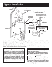
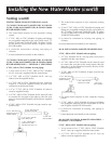
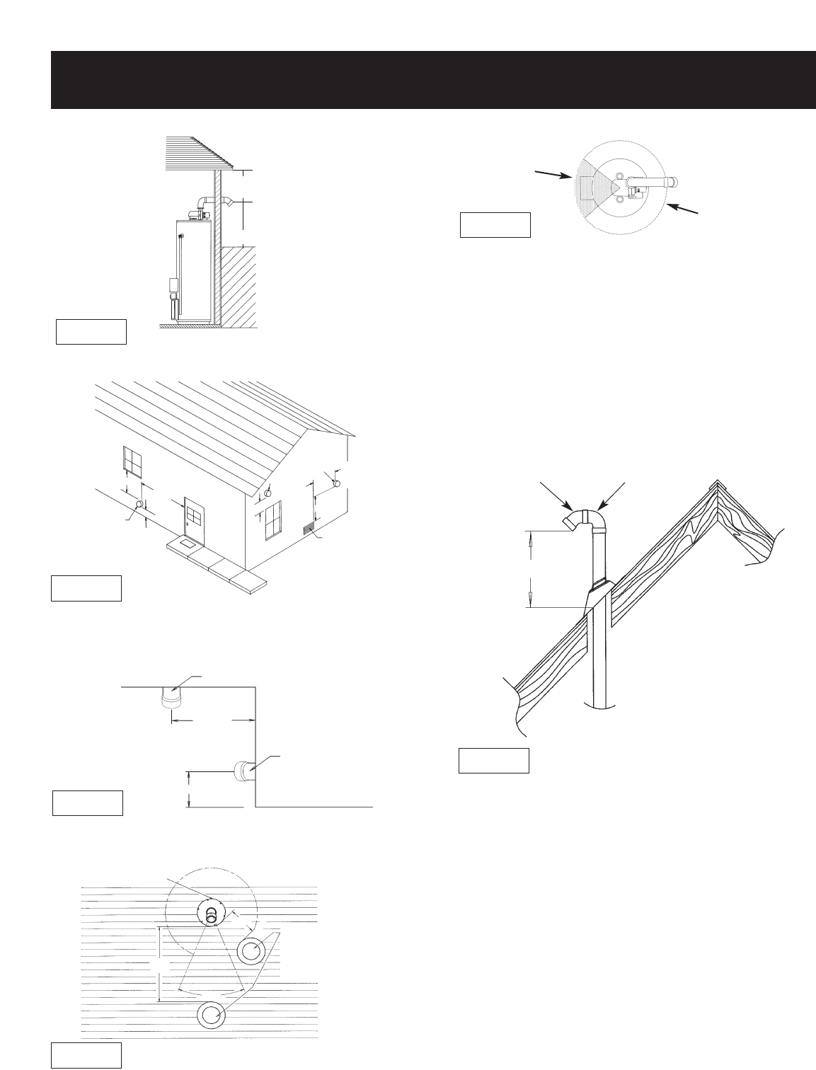
Venting Through Roof – Clearances
•
0″ clearance for 3″ (or optional 2″ and 4″) PVC, ABS, or CPVC
Schedule 40 piping from combustible surfaces.
•
The Power Vent outlet terminal shall terminate at least 18 inch-
es above the roof surface. Figure 5.
•
The location selection must provide clearances for servicing
and proper operation of the water heater. Figure 4.
•
The venting system must be installed in a manner which
allows inspection of the installation of the venting pipes and
joints as well as periodic inspection after installation as
required by ANSI Standards.
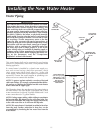
Figure 5
18
″
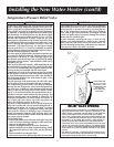
Combustion Air and Ventilation
for Appliances Located in
Unconfined Spaces
Unconfined Space is a space whose volume is not less than 50
cubic feet per 1,000 Btu per hour of the aggregate input rating of
all appliances installed in that space. Rooms communicating
directly with the space in which the appliances are installed,
through openings not furnished with doors, are considered a part
of the unconfined space.
In unconfined spaces in buildings, infiltration may be adequate
to provide air for combustion, ventilation and dilution of flue
gases. However, in buildings of tight construction (for example,
weather stripping, heavily insulated, caulked, vapor barrier, etc.),
additional air may need to be provided using the methods
described in Combustion Air and Ventilation for Appliances
Located in Confined Spaces.
B
45° VENT CAP
W/SCREEN
90° STREET ELL