


17
Installing the New Water Heater (cont’d)
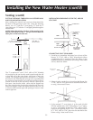
MIN. RISE
1
⁄8″
PER FIVE FEET
MIN. RISE
1
⁄
8
″
PER FIVE FEET
MIN. RISE
1
⁄8″
PER FIVE FEET
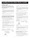
3 ELBOW
EXAMPLE
16″ MIN.
MIN. RISE
1
⁄8″
PER FIVE FEET
13
1
⁄2″ MIN.
12″ MIN.
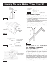
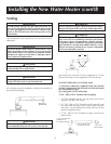
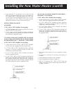
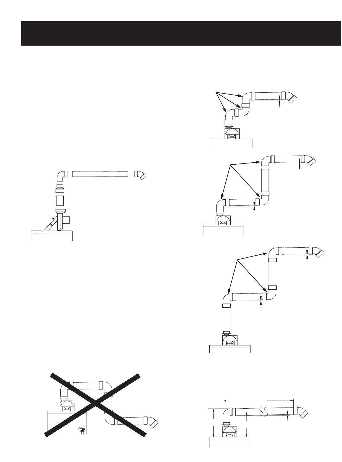
1. Horizontal runs require a minimum
1
⁄8″ rise per five feet.
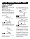
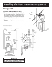
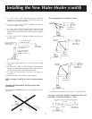
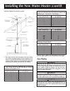
40 AND 50 GALLON MODELS 50,000 BTU/HR AND
HIGHER, 75 GALLON MODELS (3″ VENT)
VENTING SYSTEM EXAMPLE INSTALLATIONS FOR
ALL MODELS
The vent piping cannot under any circumstances be run
downhill.
The vent piping may be installed as follows:
3 ELBOW
EXAMPLE
MIN. RISE
1
⁄8″
PER FIVE FEET
MIN. RISE
1
⁄8″
PER FIVE FEET
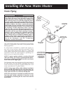
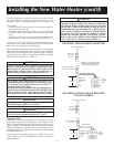
3. A 3″ PVC, ABS or CPVC Schedule 40 pipe, minimum
length of 3″ (must be supplied locally), to make vent
connection at the blower outlet.
4. A 3″ to 2″ PVC, ABS or CPVC Schedule 40 reducer
(must be supplied locally).
5. A 2″ PVC, ABS or CPVC Schedule 40-90° street ell; used
to connect the vent pipe to the reducer when the vent
pipe is to be turned horizontally off the blower (supplied
locally).
6. 2″ PVC, ABS or CPVC Schedule 40 pipe (must be sup-
plied locally).
7. The water heater requires its own (separate) venting
system.
8. 2″ and 3″ PVC, ABS, or CPVC Schedule 40 piping and
fittings are acceptable materials for the vent system on
all 40 and 50 gallon 40,000 BTU/HR models.
9. It cannot be connected to existing vent piping or
chimney.
10. It must terminate horizontally to the outdoors.
NOTE: See pages 21 and 22 for vertical venting through a
roof.
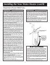
3 ELBOW
EXAMPLE
SEE CHART ON PAGE 18 FOR MAX. LENGTH
2″ PVC, ABS OR CPVC
SCHEDULE 40 90°
STREET ELBOW
2″ PVC, ABS OR CPVC
SCHEDULE 40 PIPE
VENT CAP
AND SCREEN
3″ PVC, ABS OR CPVC
SCHEDULE 40 PIPE
(MINIMUM LENGTH 3″)
3″ TO 2″ PVC, ABS OR
CPVC REDUCER