


23
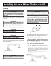
SEDIMENT TRAP
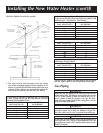
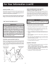
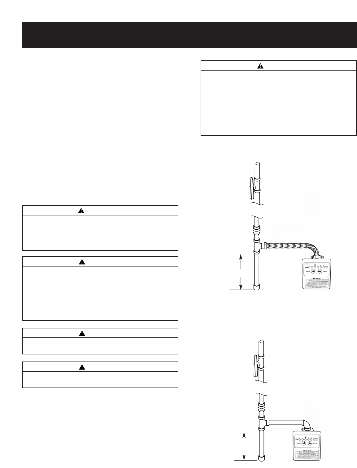
A sediment trap shall be installed as close to the inlet of the
water heater as practical at the time or water heater instal-
lation. The sediment trap shall be either a tee fitting with a
capped nipple in the bottom outlet or other device recog-
nized as an effective sediment trap. If a tee fitting is used, it
shall be installed in conformance with one of the methods
of installation shown.
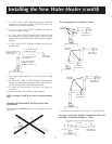
Connecting the gas piping to the gas control valve of the
water heater can be accomplished by either of the two
methods shown.
Installing the New Water Heater (cont’d)
WARNING
The appliance and its gas connection must be leak tested
before placing the appliance in operation.
WARNING
Use pipe joint compound or teflon tape marked as being resis-
tant to the action of petroleum [Propane (L.P.)] gases.
WARNING
Contaminant’s in the gas lines may cause improper
operation of the gas control valve that may result in fire
or explosion. Before attaching the gas line be sure that
all gas pipe is clean on the inside. To trap any dirt or
foreign material in the gas supply line, a drip leg (some-
times called a sediment trap) must be incorporated in
the piping. The drip leg must be readily accessible.
Install in accordance with the “Gas Piping” section.
Refer to the current edition of the National Fuel Gas
Code, ANSI Z223.1, also referred to as NFPA 54.
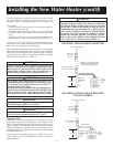
GAS PIPING WITH FLEXIBLE CONNECTOR
GAS PIPING WITH ALL BLACK IRON PIPE
TO GAS CONTROL
GROUND JOINT
UNION (OPTIONAL)
MANUAL
SHUTOFF
VALVE
GAS
CONTROL
VALVE
GAS SUPPLY PIPING
FLEXIBLE GAS CONNECTOR
LABELED AS COMPLYING
WITH ANSI STANDARDS
DRIP LEG
(SEDIMENT
TRAP)
CAP
GAS SUPPLY PIPING
MANUAL
SHUTOFF
VALVE
GAS
CONTROL
VALVE
GROUND JOINT
UNION
BLACK PIPE
DRIP LEG
(SEDIMENT
TRAP)
CAP
3″ MIN.
3″ MIN.
A gas line of sufficient size must be run to the water heater. Consult
the current edition of National Fuel Gas Code ANSI Z223.1, also
referred to as NFPA 54 and the gas company concerning pipe size.
There must be:
—A readily accessible manual shut off valve in the gas supply line
serving the water heater, and
—A drip leg (sediment trap) ahead of the gas control valve to help
prevent dirt and foreign materials from entering the gas control
valve.
—A flexible gas connector or a ground joint union between the
shutoff valve and control valve to permit servicing of the unit.
Be sure to check all the gas piping for leaks before lighting the
water heater. Use a soapy water solution, not a match or open
flame. Rinse off soapy solution and wipe dry.
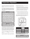
When installed at elevations above 2,000 feet, input ratings
should be reduced at the rate of 4 percent for each 1,000 feet
above sea level. Installations above 4,000 ft. require replace-
ment of the burner orifice in accordance with the National
Fuel Gas Code ANSI Z223.1 / NFPA 54.
WARNING
The appliance and its individual shutoff valve must be dis-
connected from the gas supply piping system during any pres-
sure testing of that system at test pressures in excess of
1
/2
pound per square inch (3.5kPa).
The appliance must be isolated from the gas supply piping sys-
tem by closing its individual manual shutoff valve during any
pressure testing of the gas supply piping system at test pres-
sures equal to or less than
1
/2 pound per square inch (3.5kPa).
WARNING
Failure to replace the orifice could result in improper and
inefficient operation of the appliance, producing carbon
monoxide gas in excess of safe limits, which could result in
serious injury or death. Contact your gas supplier for any
specific changes which may be required in your area.