


Combustion Air and Ventilation
for Appliances Located in
Confined Spaces
Confined Space is a space whose volume is less than 50 cubic
feet per 1,000 Btu per hour of the aggregate input rating of all
appliances installed in that space.
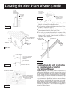
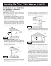
a. ALL AIR FROM INSIDE BUILDINGS:
(See Page 8 Figure 1, and Figure 6 below)
The confined space shall be provided with two permanent
openings communicating directly with an additional room(s)
of sufficient volume so that the combined volume of all spaces
meets the criteria for an unconfined space. The total input of
all gas utilization equipment installed in the combined space
shall be considered in making this determination. Each open-
ing shall have a minimum free area of one square inch per
1,000 BTU per hour of the total input rating of all gas utiliza-
tion equipment in the confined space, but not less than 100
square inches. One opening shall commence within 12 inch-
es of the top and one commencing within 12 inches of the
bottom of the enclosure.
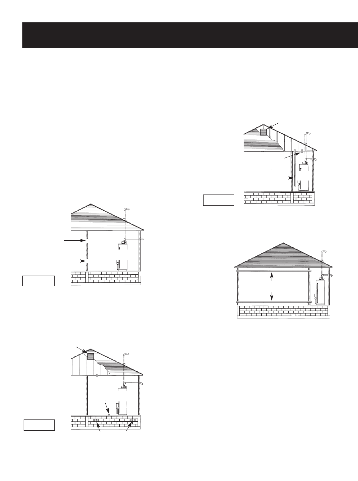
b. ALL AIR FROM OUTDOORS: (see Figures 7-9)
The confined space shall be provided with two permanent
openings, one commencing within 12 inches of the top and
one commencing within 12 inches from the bottom of the
enclosure. The openings shall communicate directly, or by
ducts, with the outdoors or spaces (crawl or attic) that freely
communicate with the outdoors.
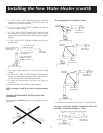
2. When communicating with the outdoors through vertical
ducts, each opening shall have a minimum free area of 1
square inch per 4,000 BTU per hour of total input rating of
all equipment in the enclosure. (See Figure 8.)
3. When communicating with the outdoors through horizon-
tal ducts, each opening shall have a minimum free area of
1 square inch per 2,000 BTU per hour of total input rating
of all equipment in the enclosure. (See Figure 9.)
4. When ducts are used, they shall be of the same cross-sec-
tional area as the free area of the openings to which they
connect. The minimum short side dimension of rectangular
air ducts shall not be less than 3 inches. (See Figure 9.)
5. Louvers and Grilles: In calculating free area, consideration
shall be given to the blocking effect of louvers, grilles or
screens protecting openings. Screens used shall not be small-
er than
1
⁄4 inch mesh. If the free area through a design of lou-
ver or grille is known, it should be used in calculating the
size opening required to provide the free area specified. If
the design and free area is not known, it may be assumed
that wood louvers will be 20-25 percent free area and metal
louvers and grilles will have 60-75 percent free area. Louvers
and grilles shall be fixed in the open position or interlocked
with the equipment so that they are opened automatically
during equipment operation.
6. Special Conditions Created by Mechanical Exhausting or
Fireplaces: Operation of exhaust fans, ventilation systems,
clothes dryers or fireplaces may create conditions requiring
special attention to avoid unsatisfactory operation of
installed gas utilization equipment.
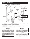
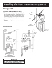
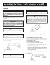
Locating the New Water Heater (cont’d)
Figure 6
Figure 8
Figure 9
Figure 7
10
1. When directly communicating with the outdoors, each
opening shall have a minimum free area of 1 square inch
per 4,000 BTU per hour of total input rating of all equip-
ment in the enclosure. (See Figure 6.)
OPENINGS
VENTILATION LOUVERS
(each end of attic)
VENT THROUGH
ROOF
WATER
HEATER
WATER
HEATER
VENT TO
OUTDOORS
VENT TO
OUTDOORS
INLET AIR
DUCT
VENTILATION LOUVERS
VENT THROUGH
ROOF
VENT THROUGH ROOF
VENT TO
OUTDOORS
VENT TO
OUTDOORS
VENT THROUGH
ROOF
VENTILATION LOUVERS
(each end of attic)
WATER
HEATER
AIR OUTLET
INLET AIR DUCT
(ends 1″ above floor)
OUTLET AIR DUCT
INLET AIR DUCT